Rigid pavement design
Lecture notes in Transportation Systems Engineering
3 August 2009
As the name implies, rigid pavements are rigid i.e, they do not flex much under
loading like flexible pavements.
They are constructed using cement concrete.
In this case, the load carrying capacity is mainly due to the rigidity ad high
modulus of elasticity of the slab (slab action).
H. M. Westergaard is considered the pioneer in providing the rational treatment
of the rigid pavement analysis.
Westergaard considered the rigid pavement slab as a thin elastic plate resting
on soil sub-grade, which is assumed as a dense liquid.
The upward reaction is assumed to be proportional to the deflection.
Base on this assumption, Westergaard defined a modulus of sub-grade
reaction  in kg/cm
 given by
 where
where  is the
displacement level taken as 0.125 cm and
is the
displacement level taken as 0.125 cm and  is the pressure sustained by the
rigid plate of 75 cm diameter at a deflection of 0.125 cm.
is the pressure sustained by the
rigid plate of 75 cm diameter at a deflection of 0.125 cm.
A certain degree of resistance to slab deflection is offered by the sub-grade.
The sub-grade deformation is same as the slab deflection.
Hence the slab deflection is direct measurement of the magnitude of the
sub-grade pressure.
This pressure deformation characteristics of rigid pavement lead Westergaard to
the define the term radius of relative stiffness  in cm is given by
the equation
in cm is given by
the equation ![[*]](file:/usr/share/latex2html/icons/crossref.gif) .
.
![\begin{displaymath}
l = \sqrt[4]{\frac{Eh^3}{12K(1-\mu^2)}}
\end{displaymath}](img7.gif) |
(1) |
where E is the modulus of elasticity of cement concrete in kg/cm (3.0
(3.0 10
10 ),
),  is the Poisson's ratio of concrete (0.15),
  is
the slab thickness in cm and is the modulus of sub-grade reaction.
is
the slab thickness in cm and is the modulus of sub-grade reaction.
Since the pavement slab has finite length and width, either the character or
the intensity of maximum stress induced by the application of a given traffic
load is dependent on the location of the load on the pavement surface.
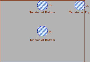
There are three typical locations namely the interior, edge and corner, where differing conditions of slab continuity exist.
These locations are termed as critical load positions.
When the interior point is loaded, only a small area of the pavement is
resisting the bending moment of the plate.
Westergaard's gives a relation for equivalent radius of the resisting section
in cm in the equation .
 |
(2) |
where  is the radius of the wheel load distribution in cm and is the
slab thickness in cm.
is the radius of the wheel load distribution in cm and is the
slab thickness in cm.
The cement concrete slab is assumed to be homogeneous and to have uniform
elastic properties with vertical sub-grade reaction being proportional to the
deflection.
Westergaard developed relationships for the stress at interior, edge and corner
regions, denoted as
 in kg/cm respectively
and given by the equation -.
in kg/cm respectively
and given by the equation -.
![\begin{displaymath}
\sigma_i=\frac{0.316 P}{h^2}\left[4 \log_{10}\left(\frac{l}{b}\right)+1.069\right]
\end{displaymath}](img16.gif) |
(3) |
![\begin{displaymath}
\sigma_e=\frac{0.572 P}{h^2}\left[4 \log_{10}\left(\frac{l}{b}\right)+0.359\right]
\end{displaymath}](img17.gif) |
(4) |
![\begin{displaymath}
\sigma_c=\frac{3 P}{h^2}\left[1-\left(\frac{a\sqrt{2}}{l}\right)^{0.6}\right]
\end{displaymath}](img18.gif) |
(5) |
where is the slab thickness in cm,  is the wheel load in kg, is the
radius of the wheel load distribution in cm, the radius of the relative
stiffness in cm and
is the wheel load in kg, is the
radius of the wheel load distribution in cm, the radius of the relative
stiffness in cm and  is the radius of the resisting
section in cm
is the radius of the resisting
section in cm
Figure:
Critical stress locations
 |
Temperature stresses are developed in cement concrete pavement due to variation
in slab temperature.
This is caused by (i) daily variation resulting in a temperature gradient
across the thickness of the slab and (ii) seasonal variation resulting in
overall change in the slab temperature.
The former results in warping stresses and the later in frictional
stresses.
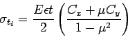
The warping stress at the interior, edge and corner regions, denoted as
 in kg/cm respectively and given
by the equation -.
in kg/cm respectively and given
by the equation -.
 |
(6) |
 |
(7) |
 |
(8) |
where
 is the modulus of elasticity of concrete in kg/cm (310),
 is the thermal coefficient of concrete per
  C (110
 )
)
 is the temperature difference between the top and bottom of the slab,
 and
and  are the coefficient based on
  in the desired direction
and
in the desired direction
and  right angle to the desired direction,
is the Poisson's ration (0.15),
is the radius of the contact area and
is the radius of the relative stiffness.
right angle to the desired direction,
is the Poisson's ration (0.15),
is the radius of the contact area and
is the radius of the relative stiffness.
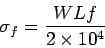
The frictional stress  in kg/cm is given by the equation
 |
(9) |
where
 is the unit weight of concrete in kg/cm (2400),
 is the coefficient of sub grade friction (1.5) and
 is the length of the slab in meters.
The cumulative effect of the different stress give rise to the following thee
critical cases
- Summer, mid-day: The critical stress is for edge region given by

- Winter, mid-day: The critical combination of stress is for the edge
region given by

- Mid-nights: The critical combination of stress is for the corner
region given by

The purpose of the expansion joint is to allow the expansion of the pavement
due to rise in temperature with respect to construction temperature.
The design consideration are:
- Provided along the longitudinal direction,
- design involves finding the joint spacing for a given expansion joint
thickness (say 2.5 cm specified by IRC) subjected to some maximum spacing (say
140 as per IRC)
Figure:
Expansion joint
 |
The purpose of the contraction joint is to allow the contraction of the slab
due to fall in slab temperature below the construction temperature.
The design considerations are:
Figure:
Contraction joint
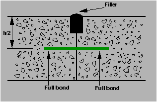 |
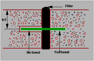
The purpose of the dowel bar is to effectively transfer the load between two
concrete slabs and to keep the two slabs in same height.
The dowel bars are provided in the direction of the traffic (longitudinal).
The design considerations are:
- Mild steel rounded bars,
- bonded on one side and free on other side
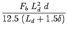
Bradbury's analysis gives load transfer capacity of single dowel bar in shear,
bending and bearing as follows:
where,
is the load transfer capacity of a single dowel bar in shear  , bending
and bearing ,
, bending
and bearing ,
 is the diameter of the bar in cm,
 is the length of the embedment of dowel bar in cm,
 is the joint width in cm,
 are the permissible stress in shear, bending and bearing for the
dowel bar in kg/cm.
are the permissible stress in shear, bending and bearing for the
dowel bar in kg/cm.
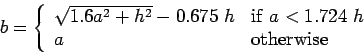
- Step
Find the length of the dowel bar embedded in slab by equating
Eq. =Eq. , i.e.
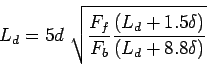 |
(14) |
- Step
Find the load transfer capacities
 ,
,  , and
, and  of single dowel
bar with the
of single dowel
bar with the
- Step
Assume load capacity of dowel bar is 40 percent wheel load, find the
load capacity factor f as
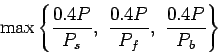 |
(15) |
- Step
Spacing of the dowel bars.
- Effective distance upto which effective load transfer take place is given
by
 , where is the radius of relative stiffness.
- Assume a linear variation of capacity factor of 1.0 under load to 0 at
.
- Assume a dowel spacing and find the capacity factor of the above
spacing.
- Actual capacity factor should be greater than the required capacity
factor.
- If not, do one more iteration with new spacing.
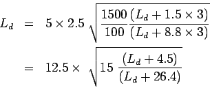
Design size and spacing of dowel bars at an expansion joint of concrete
pavement of thickness 25 cm.
Given the radius of relative stiffness of 80 cm. design wheel load 5000 kg.
Load capacity of the dowel system is 40 percent of design wheel load.
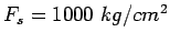
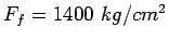
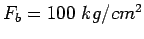
Joint width is 2.0 cm and the permissible stress in shear, bending and bearing
stress in dowel bars are 1000,1400 and 100  respectively.
Given, 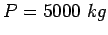 ,
,  ,
,  ,
,  ,
,
 ,
,
 and
and
 ; and assume
  diameter.
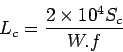
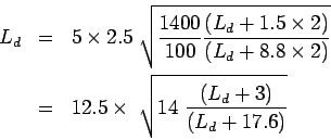
Step-1: length of the dowel bar
Solve for by trial and error:
put
 put
put
 put
put
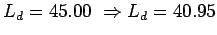
 Minimum length of the dowel bar is
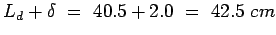 , So,
provide
, So,
provide  long and
  . Therefore
 .
.
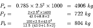
Step 2: Find the load transfer capacity of single dowel bar
Therefore, the required load transfer capacity
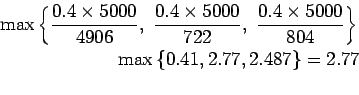
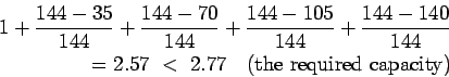
Step-3 : Find the required spacing:
Effective distance of load transfer
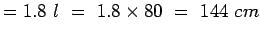 .
Assuming
.
Assuming  spacing,
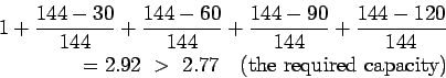
Actual capacity is
Therefore assume  spacing and now the actual capacity is
Therefore provide mild steel dowel bars of length
 center to center.
In contrast to dowel bars, tie bars are not load transfer devices, but serve as
a means to tie two slabs.
Hence tie bars must be deformed or hooked and must be firmly anchored into the
concrete to function properly.
They are smaller than dowel bars and placed at large intervals.
They are provided across longitudinal joints.
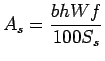
- Step
Diameter and spacing: The diameter and the spacing is first found out by
equating the total sub-grade friction tot he total tensile stress for a unit
length (one meter).
Hence the area of steel per one meter in
 is given by:
 |
|
|
|
 |
|
|
(16) |
where,
is the width of the pavement panel in  ,
is the depth of the pavement in
,
is the depth of the pavement in  ,
is the unit weight of the concrete (assume
,
is the unit weight of the concrete (assume 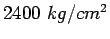 ),
is the coefficient of friction (assume
),
is the coefficient of friction (assume  ), and
 is the allowable working tensile stress in steel (assume
 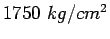 ).
Assume
).
Assume  to
to  bars for the design.
- Step
Length of the tie bar: Length of the tie bar is twice the length needed
to develop bond stress equal to the working tensile stress and is given by:
 |
|
|
(17) |
where,
is the diameter of the bar, is the allowable tensile stress in
, and  is the allowable bond stress and can be assumed for plain
and deformed bars respectively as
is the allowable bond stress and can be assumed for plain
and deformed bars respectively as  and
and  .
.
A cement concrete pavement of thickness 18 cm, has two lanes of 7.2 m with a
joint. Design the tie bars.
(Solution:)
Given h=18 cm, b=7.2/2=3.6m,

 .
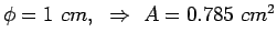
Step 1: diameter and spacing: Get
.
Step 1: diameter and spacing: Get  from
from
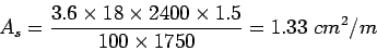
Assume
 . Therefore spacing is
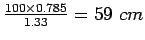 , say
, say  Step 2: Length of the bar: Get
  from
from
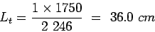
[Ans] Use  tie bars of length of

Design of rigid pavements is based on Westergaard's analysis, where modulus of
subgrade reaction, radius of relative stiffness, radius of wheel load
distribution are used.
For critical design, a combination of load stress, frictional stress and
warping stress is considered.
Different types of joints are required like expansion and contraction joints.
Their design is also dealt with.
- Design size and spacing of dowel bars at an expansion joint of concrete
pavement of thickness 20 cm.
Given the radius of relative stiffness of 90 cm. design wheel load 4000 kg.
Load capacity of the dowel system is 40 percent of design wheel load.
Joint width is 3.0 cm and the permissible stress in shear, bending and bearing
stress in dowel bars are 1000,1500 and 100 respectively.
- Design the length and spacing of tie bars given that the pavement
thickness is 20cm and width of the road is 7m with one longitudinal joint.
The unit weight of concrete is 2400
 , the coefficient of friction is
1.5, allowable working tensile stress in steel is 1750 , and bond
stress of deformed bars is 24.6 .
, the coefficient of friction is
1.5, allowable working tensile stress in steel is 1750 , and bond
stress of deformed bars is 24.6 .
Given,  ,
,  ,
,  ,
,  ,
,
,
,
 and
; and assume diameter.
and
; and assume diameter.
Step-1: length of the dowel bar ,
Solving for by trial and error, it is =39.5cm
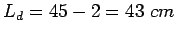
Minimum length of the dowel bar is
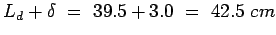 , So,
provide long and . Therefore
, So,
provide long and . Therefore
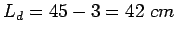 .
.
Step 2: Find the load transfer capacity of single dowel bar
Therefore, the required load transfer capacity (refer equation)
Step-3 : Find the required spacing:
Effective distance of load transfer
 .
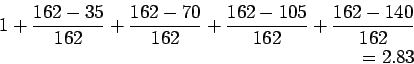
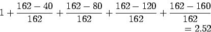
Assuming spacing,
.
Assuming spacing,
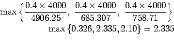
Actual capacity is
Assuming 40cm spacing, capacity is,
So we should consider 2.52>2.335 as it is greater and more near to other value.
Therefore provide mild steel dowel bars of length
 center to center.
- 2.Given h=20 cm, b=7/2=3.5m,
 .
Step 1: diameter and spacing:
.
Step 1: diameter and spacing:
Assume
. Therefore spacing is
 , say
Step 2: Length of the bar:
, say
Step 2: Length of the bar:
[Ans] Use tie bars of length of

No References!
Prof. Tom V. Mathew
2009-08-03