Traffic signal design-II
Lecture notes in Transportation Systems Engineering
3 August 2009
In the previous chapter, a simple design of cycle time was discussed.
Here we will discuss how the cycle time is divided in a phase.
The performance evaluation of a signal is also discussed.
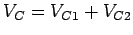
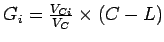
Green splitting or apportioning of green time is the proportioning of effective
green time in each of the signal phase.
The green splitting is given by,
![\begin{displaymath}
g_i = \left[\frac{V_ci}{\sum_{i=1}^n{V_{ci}}}\right]\times t_g
\end{displaymath}](img1.gif) |
(1) |
where  is the critical lane volume and
  is the total effective green
time available in a cycle.
This will be cycle time minus the total lost time for all the phases.
Therefore,
is the total effective green
time available in a cycle.
This will be cycle time minus the total lost time for all the phases.
Therefore,
 |
(2) |
where  is the cycle time in seconds,
  is the number of phases, and
  is the lost time per phase.
If lost time is different for different phases, then cycle time can be computed
as follows.
is the lost time per phase.
If lost time is different for different phases, then cycle time can be computed
as follows.
 |
(3) |
where  is the lost time for phase
  , is the number of phases and
is the lost time in seconds.
Actual greentime can be now found out as,
, is the number of phases and
is the lost time in seconds.
Actual greentime can be now found out as,
 |
(4) |
where  is the actual green time,
  is the effective green time
available,
is the effective green time
available,  is the amber time, and
  is the lost time for phase .
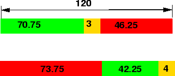
The phase diagram with flow values of an intersection with two phases is shown
in figure 1.
Figure 1:
Phase diagram for an intersection
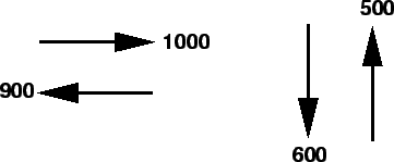 |
The lost time and yellow time for the first phase is 2.5 and 3 seconds
respectively. For the second phase the lost time and yellow time are 3.5 and 4
seconds respectively.
If the cycle time is 120 seconds, find the green time allocated for the two
phases.
- Critical lane volume for the first phase,
 = 1000 vph.
- Critical lane volume for the second phase,
 = 600 vph.
- The sum of the critical lane volumes,
 = 1000+600 =
1600 vph.
= 1000+600 =
1600 vph.
- Effective green time can be found out from equationas
 =120-(2.5-3.5)= 114 seconds.
- Green time for the first phase,
 can be found out from
equationas
can be found out from
equationas
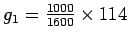 = 71.25 seconds.
- Green time for the second phase,
 can be found out from
equationas
can be found out from
equationas
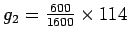 = 42.75
seconds.
= 42.75
seconds.
- Actual green time can be found out from equationThus actual green time for the first phase,
 = 71.25-3+2.5 = 70.75
seconds.
= 71.25-3+2.5 = 70.75
seconds.
- Actual green time for the second phase,
 = 42.75-3+2.5 = 42.25
seconds.
= 42.75-3+2.5 = 42.25
seconds.
- The phase diagram is as shown in figure 2.
Figure 2:
Timing diagram
 |
Pedestrian crossing requirements can be taken care by two ways; by suitable
phase design or by providing an exclusive pedestrian phase.
It is possible in some cases to allocate time for the pedestrians without
providing an exclusive phase for them.
For example, consider an intersection in which the traffic moves from north to
south and also from east to west.
If we are providing a phase which allows the traffic to flow only in
north-south direction, then the pedestrians can cross in east-west direction
and vice-versa.
However in some cases, it may be necessary to provide an exclusive pedestrian
phase.
In such cases, the procedure involves computation of time duration of
allocation of pedestrian phase.
Green time for pedestrian crossing  can be found out by,
 |
(5) |
where is the minimum safe time required for the pedestrians to cross,
often referred to as the ``pedestrian green time",  is the start-up lost
time,
is the start-up lost
time,  is the crossing distance in metres, and
  is the walking speed
of pedestrians which is about 15th percentile speed.
The start-up lost time can be assumed as 4.7 seconds and the walking
speed can be assumed to be 1.2 m/s.
is the walking speed
of pedestrians which is about 15th percentile speed.
The start-up lost time can be assumed as 4.7 seconds and the walking
speed can be assumed to be 1.2 m/s.
Performance measures are parameters used to evaluate the effectiveness of the
design.
There are many parameters involved to evaluate the effectiveness of the design
and most common of these include delay, queuing, and stops.
Delay is a measure that most directly relates the driver's experience.
It describes the amount of time that is consumed while traversing the
intersection.
The figure 3 shows a plot of distance versus time for the progress of
one vehicle.
Figure 3:
Illustration of delay measures
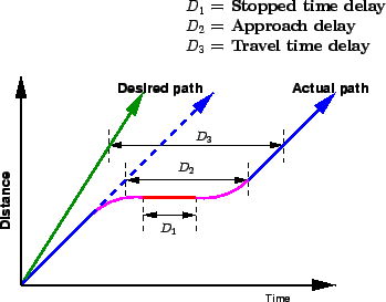 |
The desired path of the vehicle as well as the actual progress of the vehicle
is shown.
There are three types of delay as shown in the figure.
They are stopped delay, approach delay and control delay.
Stopped time delay includes only the time at which the vehicle is
actually stopped waiting at the red signal.
It starts when the vehicle reaches a full stop, and ends when the vehicle
begins to accelerate.
Approach delay includes the stopped time as well as the time lost due to
acceleration and deceleration.
It is measured as the time differential between the actual path of the vehicle,
and path had there been green signal.
Control delay is measured as the difference between the time taken for
crossing the intersection and time taken to traverse the same section, had been
no intersection.
For a signalized intersection, it is measured at the stop-line as the vehicle
enters the intersection.
Among various types of delays, stopped delay is easy to derive and often used
as a performance indicator and will be discussed.
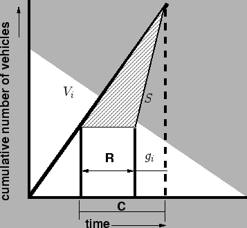
Vehicles are not uniformly coming to an intersection.
i.e., they are not approaching the intersection at constant time intervals.
They come in a random manner.
This makes the modeling of signalized intersection delay complex.
Most simple of the delay models is Webster's delay model.
It assumes that the vehicles are arriving at a uniform rate.
Plotting a graph with time along the x-axis and cumulative vehicles along the
y-axis we get a graph as shown in figure 4.
The delay per cycle is shown as the area of the hatched portion in the figure.
Figure 4:
Graph between time and cumulative number of vehicles at an
intersection
 |
Webster derived an expression for delay per cycle based on this, which is as
follows.
![\begin{displaymath}
d_i = \frac{\frac{C}{2}[1-\frac{g_i}{C}]^2}{1-\frac{V_i}{S}}
\end{displaymath}](img35.gif) |
(6) |
where is the effective green time, is the cycle length,  is the
critical flow for that phase, and
is the
critical flow for that phase, and  is the saturation flow.
Delay is the most frequently used parameter of effectiveness for intersections.
Other measures like length of queue at any given time ( ) and number of
stops are also useful.
Length of queue is used to determine when a given intersection will impede the
discharge from an adjacent upstream intersection.
The number of stops made is an important input parameter in air quality models.
) and number of
stops are also useful.
Length of queue is used to determine when a given intersection will impede the
discharge from an adjacent upstream intersection.
The number of stops made is an important input parameter in air quality models.
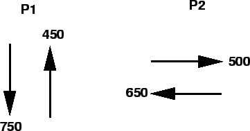
The traffic flow for a four-legged intersection is as shown in
figure 5.
Figure 5:
Traffic flow for a typical four-legged intersection
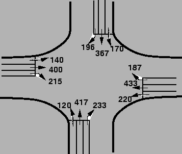 |
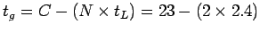
Given that the lost time per phase is 2.4 seconds, saturation headway is 2.2
seconds, amber time is 3 seconds per phase, find the cycle length, green time
and performance measure(delay per cycle).
Assume critical  ratio as 0.9.
- The phase plan is as shown in figure 6.
Figure 6:
Phase plan
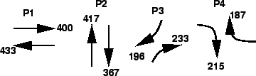 |
Sum of critical lane volumes is the sum of maximum lane volumes in each phase,
 = 433+417+233+215 = 1298 vph.
- Saturation flow rate,
 from equation=
 = 1637 vph.
 =
=
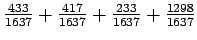 = 0.793.
- Cycle length can be found out from the equation as C=
 = 80.68 seconds
 80 seconds.
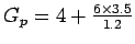
- The effective green time can be found out as
 = 80-(4
 2.4)= 70.4 seconds, where
  is
the lost time for that phase = 4 2.4.
is
the lost time for that phase = 4 2.4.
- Green splitting for the phase 1 can be found out as = 70.4 [
 ] = 22.88 seconds.
- Similarly green splitting for the phase 2,
![$g_2 = 70.4 \times
[\frac{417}{1298}]$](img53.gif) = 22.02 seconds.
= 22.02 seconds.
- Similarly green splitting for the phase 3,
![$g_3 = 70.4 \times
[\frac{233}{1298}]$](img54.gif) = 12.04 seconds.
= 12.04 seconds.
- Similarly green splitting for the phase 4,
![$g_4 = 70.4 \times
[\frac{215}{1298}]$](img55.gif) = 11.66 seconds.
= 11.66 seconds.
- The actual green time for phase 1 from equationas = 22.88-3+2.4 23 seconds.
- Similarly actual green time for phase 2, = 22.02-3+2.4
23 seconds.
- Similarly actual green time for phase 3,
 = 12.04-3+2.4
13 seconds.
= 12.04-3+2.4
13 seconds.
- Similarly actual green time for phase 4,
 = 11.66-3+2.4
12 seconds.
= 11.66-3+2.4
12 seconds.
- Pedestrian time can be found out from as
 = 21.5 seconds.
The phase diagram is shown in figure 7.
= 21.5 seconds.
The phase diagram is shown in figure 7.
Figure 7:
Timing diagram
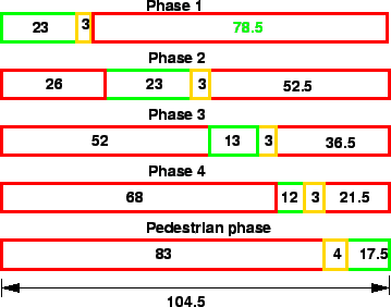 |
The actual cycle time will be the sum of actual green time plus amber time plus actual red time for any phase.
Therefore, for phase 1, actual cycle time = 23+3+78.5 = 104.5 seconds.
- Delay at the intersection in the east-west direction can be found out
from equationas
- Delay at the intersection in the west-east direction can be found out
from equation,as
![\begin{displaymath}
d_{WE} =\frac{\frac{104.5}{2}[1-\frac{23-2.4+3}{104.5}]^2}{1-\frac{400}{1637}}=41.44
sec/cycle.
\end{displaymath}](img61.gif) |
(7) |
- Delay at the intersection in the north-south direction can be found out
from equation,
![\begin{displaymath}
d_{NS} =
\frac{\frac{104.5}{2}[1-\frac{23-2.4+3}{104.5}]^2}{1-\frac{367}{1637}}=40.36
sec/cycle.
\end{displaymath}](img62.gif) |
(8) |
- Delay at the intersection in the south-north direction can be found out
from equation,
![\begin{displaymath}
d_{SN} =
\frac{\frac{104.5}{2}[1-\frac{23-2.4+3}{104.5}]^2}{1-\frac{417}{1637}}=42.018
sec/cycle.
\end{displaymath}](img63.gif) |
(9) |
- Delay at the intersection in the south-east direction can be found out
from equation,
![\begin{displaymath}
d_{SE} =
\frac{\frac{104.5}{2}[1-\frac{13-2.4+3}{104.5}]^2}{1-\frac{233}{1637}}=46.096
sec/cycle.
\end{displaymath}](img64.gif) |
(10) |
- Delay at the intersection in the north-west direction can be found out
from equation,
![\begin{displaymath}
d_{NW} =
\frac{\frac{104.5}{2}[1-\frac{13-2.4+3}{104.5}]^2}{1-\frac{196}{1637}}=44.912
sec/cycle.
\end{displaymath}](img65.gif) |
(11) |
- Delay at the intersection in the west-south direction can be found out
from equation,
![\begin{displaymath}
d_{WS} =
\frac{\frac{104.5}{2}[1-\frac{12-2.4+3}{104.5}]^2}{1-\frac{215}{1637}}=46.52
sec/cycle.
\end{displaymath}](img66.gif) |
(12) |
- Delay at the intersection in the east-north direction can be found out
from equation,
![\begin{displaymath}
d_{EN} =
\frac{\frac{104.5}{2}[1-\frac{12-2.4+3}{104.5}]^2}{1-\frac{187}{1637}}=45.62
sec/cycle.
\end{displaymath}](img67.gif) |
(13) |
Green splitting is done by proportioning the green time among various phases
according to the critical volume of the phase.
Pedestrian phases are provided by considering the walking speed and start-up
lost time.
Like other facilities, signals are also assessed for performance, delay being
th e important parameter used.
- Table shows the traffic flow for a four-legged intersection. The lost
time per phase is 2.4 seconds, saturation headway is 2.2 seconds, amber time is
3 seconds per phase. Find the cycle length, green time and performance measure.
Assume critical volume to capacity ratio as 0.85. Draw the phasing and timing
diagrams.
| From |
To |
Flow(veh/hr) |
| North |
South |
750 |
| East |
West |
650 |
| West |
East |
500 |
- Given, saturation headway is 2.2 seconds, total lost time per phase
() is 2.4 seconds, saturation flow =
= 1636.36 veh/hr.
Phasing diagram can be assumed as in figure 9.
Figure 8:
Phase diagram
 |
- Cycle time can be found from equation=
 as negative.
- Hence the traffic flowing from north to south can be allowed to flow into
two lanes.
Figure 9:
Phase diagram
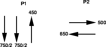 |
- Now cycle time can be find out as
 = 22.95 or 23 seconds.
- The effective green time ,
 =
18.2 seconds.
=
18.2 seconds.
- This green time can be split into two phases as,
For phase 1,
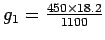 = 7.45 seconds.
For phase 2,
= 7.45 seconds.
For phase 2,
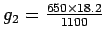 = 10.75 seconds.
Now actual green time , = minus amber time plus lost time.
Therefore, = 7.45-3+2.4 = 6.85 seconds.
= 10.75-3+2.4 = 10.15 seconds.
= 10.75 seconds.
Now actual green time , = minus amber time plus lost time.
Therefore, = 7.45-3+2.4 = 6.85 seconds.
= 10.75-3+2.4 = 10.15 seconds.
- Timing diagram is as shown in figure 10
Figure 10:
Timing diagram
 |
- Delay at the intersection in the east-west direction can be found out
from equationas
![\begin{displaymath}
d_{EW} =\frac{\frac{23}{2}[1-\frac{10.75-2.4+3}{23}]^2}{1-\frac{650}{1636.36}}=
4.892sec/cycle.
\end{displaymath}](img76.gif) |
(14) |
- Delay at the intersection in the west-east direction can be found out
from equation,as
![\begin{displaymath}
d_{WE} =\frac{\frac{23}{2}[1-\frac{10.75-2.4+3}{23}]^2}{1-\frac{500}{1636.36}}=
4.248sec/cycle.
\end{displaymath}](img77.gif) |
(15) |
- Delay at the intersection in the north-south direction can be found out
from equation,
![\begin{displaymath}
d_{NS} =
\frac{\frac{23}{2}[1-\frac{7.45-2.4+3}{23}]^2}{1-\frac{750}{1636.36}}=8.97sec/cycle.
\end{displaymath}](img78.gif) |
(16) |
- Delay at the intersection in the south-north direction can be found out
from equation,
![\begin{displaymath}
d_{SN} =
\frac{\frac{23}{2}[1-\frac{7.45-2.4+3}{23}]^2}{1-\frac{450}{1636.36}}=6.703sec/cycle.
\end{displaymath}](img79.gif) |
(17) |
- 1
William R McShane, Roger P Roesss, and Elena S Prassas.
Traffic Engineering.
Prentice-Hall, Inc, Upper Saddle River, New Jesery, 1998.
Prof. Tom V. Mathew
2009-08-03
![\begin{displaymath}
d_{EW} =\frac{\frac{104.5}{2}[1-\frac{23-2.4+3}{104.5}]^2}{1-\frac{433}{1637}} \nonumber
=42.57sec/cycle. \nonumber
\end{displaymath}](img60.gif)