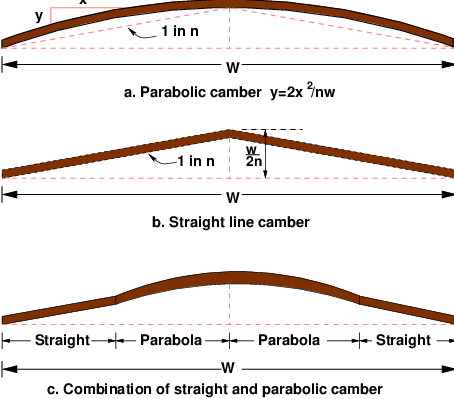
Figure 1: Different types of camber
The features of the cross-section of the pavement influences the life of the pavement as well as the riding comfort and safety. Of these, pavement surface characteristics affect both of these. Camber,kerbs, and geometry of various cross-sectional elements are important aspects to be considered in this regard. They are explained briefly in this chapter.
For safe and comfortable driving four aspects of the pavement surface are important; the friction between the wheels and the pavement surface, smoothness of the road surface, the light reflection characteristics of the top of pavement surface, and drainage to water.
Friction between the wheel and the pavement surface is a crucial factor in the design of horizontal curves and thus the safe operating speed. Further, it also affect the acceleration and deceleration ability of vehicles. Lack of adequate friction can cause skidding or slipping of vehicles.
Various factors that affect friction are:
The frictional force that develops between the wheel and the pavement is the load acting multiplied by a factor called the coefficient of friction and denoted as f. The choice of the value of f is a very complicated issue since it depends on many variables. IRC suggests the coefficient of longitudinal friction as 0.35-0.4 depending on the speed and coefficient of lateral friction as 0.15. The former is useful in sight distance calculation and the latter in horizontal curve design.
It is always desirable to have an even surface, but it is seldom possible to have such a one. Even if a road is constructed with high quality pavers, it is possible to develop unevenness due to pavement failures. Unevenness affect the vehicle operating cost, speed, riding comfort, safety, fuel consumption and wear and tear of tyres.
Unevenness index is a measure of unevenness which is the cumulative measure of vertical undulations of the pavement surface recorded per unit horizontal length of the road. An unevenness index value less than 1500 mm/km is considered as good, a value less than 2500 mm.km is satisfactory up to speed of 100 kmph and values greater than 3200 mm/km is considered as uncomfortable even for 55 kmph.
It is necessary that the road surface should be visible at night and reflection of light is the factor that answers it.
The pavement surface should be absolutely impermeable to prevent seepage of water into the pavement layers. Further, both the geometry and texture of pavement surface should help in draining out the water from the surface in less time.
Camber or cant is the cross slope provided to raise middle of the road surface in the transverse direction to drain off rain water from road surface. The objectives of providing camber are:
Too steep slope is undesirable for it will erode the surface. Camber is measured in 1 in n or n% (Eg. 1 in 50 or 2%) and the value depends on the type of pavement surface. The values suggested by IRC for various categories of pavement is given in Table 1. The common types of camber are parabolic, straight, or combination of them (Figure 1)
| Surface | Heavy | Light |
| type | rain | rain |
| Concrete/Bituminous | 2 % | 1.7 % |
| Gravel/WBM | 3 % | 2.5 % |
| Earthen | 4 % | 3.0 % |
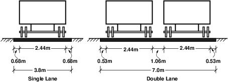
Width of the carriage way or the width of the pavement depends on the width of the traffic lane and number of lanes. Width of a traffic lane depends on the width of the vehicle and the clearance. Side clearance improves operating speed and safety. The maximum permissible width of a vehicle is 2.44 and the desirable side clearance for single lane traffic is 0.68 m. This require minimum of lane width of 3.75 m for a single lane road (Figure 2a). However, the side clearance required is about 0.53 m, on either side and 1.06 m in the center. Therefore, a two lane road require minimum of 3.5 meter for each lane (Figure 2b). The desirable carriage way width recommended by IRC is given in Table 2
| Single lane | 3.75 |
| Two lane, no kerbs | 7.0 |
| Two lane, raised kerbs | 7.5 |
| Intermediate carriage | 5.5 |
| Multi-lane | 3.5 |
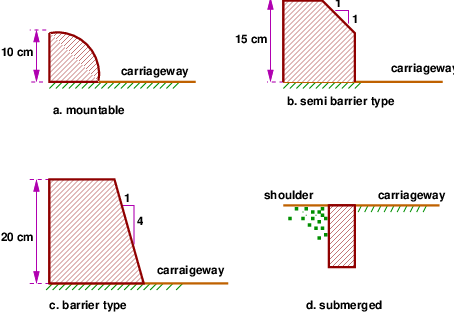
Kerbs indicate the boundary between the carriage way and the shoulder or islands or footpaths. Different types of kerbs are (Figure 3):
The portion of the road beyond the carriageway and on the roadway can be generally called road margin. Various elements that form the road margins are given below.
Shoulders are provided along the road edge and is intended for accommodation of stopped vehicles, serve as an emergency lane for vehicles and provide lateral support for base and surface courses. The shoulder should be strong enough to bear the weight of a fully loaded truck even in wet conditions. The shoulder width should be adequate for giving working space around a stopped vehicle. It is desirable to have a width of 4.6 m for the shoulders. A minimum width of 2.5 m is recommended for 2-lane rural highways in India.
Parking lanes are provided in urban lanes for side parking. Parallel parking is preferred because it is safe for the vehicles moving on the road. The parking lane should have a minimum of 3.0 m width in the case of parallel parking.
Bus bays are provided by recessing the kerbs for bus stops. They are provided so that they do not obstruct the movement of vehicles in the carriage way. They should be at least 75 meters away from the intersection so that the traffic near the intersections is not affected by the bus-bay.
Service roads or frontage roads give access to access controlled highways like freeways and expressways. They run parallel to the highway and will be usually isolated by a separator and access to the highway will be provided only at selected points. These roads are provided to avoid congestion in the expressways and also the speed of the traffic in those lanes is not reduced.
Cycle tracks are provided in urban areas when the volume of cycle traffic is high Minimum width of 2 meter is required, which may be increased by 1 meter for every additional track.
Footpaths are exclusive right of way to pedestrians, especially in urban areas. They are provided for the safety of the pedestrians when both the pedestrian traffic and vehicular traffic is high. Minimum width is 1.5 meter and may be increased based on the traffic. The footpath should be either as smooth as the pavement or more smoother than that to induce the pedestrian to use the footpath.
They are provided at the edge of the shoulder usually when the road is on an embankment. They serve to prevent the vehicles from running off the embankment, especially when the height of the fill exceeds 3 m. Various designs of guard rails are there. Guard stones painted in alternate black and white are usually used. They also give better visibility of curves at night under headlights of vehicles.
Width of formation or roadway width is the sum of the widths of pavements or carriage way including separators and shoulders. This does not include the extra land in formation/cutting. The values suggested by IRC are given in Table 3.
| Road | Roadway width in m
| |
| classification | Plain and | Mountainous and |
| rolling terrain | steep terrain | |
| NH/SH | 12 | 6.25-8.8 |
| MDR | 9 | 4.75 |
| ODR | 7.5-9.0 | 4.75 |
| VR | 7.5 | 4.0 |
Right of way (ROW) or land width is the width of land acquired for the road, along its alignment. It should be adequate to accommodate all the cross-sectional elements of the highway and may reasonably provide for future development. To prevent ribbon development along highways, control lines and building lines may be provided. Control line is a line which represents the nearest limits of future uncontrolled building activity in relation to a road. Building line represents a line on either side of the road, between which and the road no building activity is permitted at all. The right of way width is governed by:
| Road | Roadway width in m
| |
| classification | Plain and | Mountainous and |
| rolling terrain | steep terrain | |
| Open areas
| ||
| NH/SH | 45 | 24 |
| MDR | 25 | 18 |
| ODR | 15 | 15 |
| VR | 12 | 9 |
| Built-up areas
| ||
| NH/SH | 30 | 20 |
| MDR | 20 | 15 |
| ODR | 15 | 12 |
| VR | 10 | 9 |
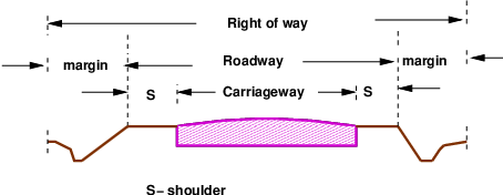
The importance of reserved land is emphasized by the following. Extra width of land is available for the construction of roadside facilities. Land acquisition is not possible later, because the land may be occupied for various other purposes (buildings, business etc.) The normal ROW requirements for built up and open areas as specified by IRC is given in Table 4 A typical cross section of a ROW is given in Figure 4.
The characteristics of cross-sectional elements are important in highway geometric design because they influence the safety and comfort. Camber provides for drainage, frictional resistance and reflectivity for safety etc. The road elements such as kerb, shoulders, carriageway width etc. should be adequate enough for smooth, safe and efficient movement of traffic. IRC has recommended the minimum values for all these cross-sectional elements.
I wish to thank several of my students and staff of NPTEL for their contribution in this lecture. I also appreciate your constructive feedback which may be sent to tvm@civil.iitb.ac.in
Prof. Tom V. Mathew
Department of Civil Engineering
Indian Institute of Technology Bombay, India
____________________________________________________________________________________________
Thu Jan 10 12:41:35 IST 2019