where Δ is the displacement level taken as 0.125 cm and p
is the pressure sustained by the rigid plate of 75 cm diameter at a deflection of 0.125
cm.
where Δ is the displacement level taken as 0.125 cm and p
is the pressure sustained by the rigid plate of 75 cm diameter at a deflection of 0.125
cm.
As the name implies, rigid pavements are rigid i.e, they do not flex much under loading like flexible pavements. They are constructed using cement concrete. In this case, the load carrying capacity is mainly due to the rigidity ad high modulus of elasticity of the slab (slab action). H. M. Westergaard is considered the pioneer in providing the rational treatment of the rigid pavement analysis.
Westergaard considered the rigid pavement slab as a thin elastic plate resting on soil sub-grade, which
is assumed as a dense liquid. The upward reaction is assumed to be proportional to the
deflection. Base on this assumption, Westergaard defined a modulus of sub-grade reaction K
in kg/cm3 given by K = where Δ is the displacement level taken as 0.125 cm and p
is the pressure sustained by the rigid plate of 75 cm diameter at a deflection of 0.125
cm.
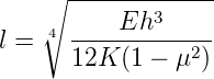
A certain degree of resistance to slab deflection is offered by the sub-grade. The sub-grade deformation is same as the slab deflection. Hence the slab deflection is direct measurement of the magnitude of the sub-grade pressure. This pressure deformation characteristics of rigid pavement lead Westergaard to the define the term radius of relative stiffness l in cm is given by the equation 1.
 | (1) |
where E is the modulus of elasticity of cement concrete in kg/cm2 (3.0×10⁵), μ is the Poisson’s ratio of concrete (0.15), h is the slab thickness in cm and K is the modulus of sub-grade reaction.
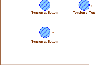
Since the pavement slab has finite length and width, either the character or the intensity of maximum stress induced by the application of a given traffic load is dependent on the location of the load on the pavement surface. There are three typical locations namely the interior, edge and corner, where differing conditions of slab continuity exist. These locations are termed as critical load positions.
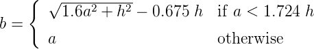
When the interior point is loaded, only a small area of the pavement is resisting the bending moment of the plate. Westergaard’s gives a relation for equivalent radius of the resisting section in cm in the equation 2.
 | (2) |
where a is the radius of the wheel load distribution in cm and h is the slab thickness in cm.
The cement concrete slab is assumed to be homogeneous and to have uniform elastic properties with vertical sub-grade reaction being proportional to the deflection. Westergaard developed relationships for the stress at interior, edge and corner regions, denoted as σi, σe, σc in kg/cm2 respectively and given by the equation 3-5.
![0.316 P [ ( l) ]
σi = ----2--- 4 log10 - + 1.069
h b](web3x.png) | (3) |
![[ ( ) ]
0.572-P- l
σe = h2 4 log10 b + 0.359](web4x.png) | (4) |
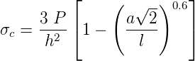 | (5) |
where h is the slab thickness in cm, P is the wheel load in kg, a is the radius of the wheel load distribution in cm, l the radius of the relative stiffness in cm and b is the radius of the resisting section in cm
Temperature stresses are developed in cement concrete pavement due to variation in slab temperature. This is caused by (i) daily variation resulting in a temperature gradient across the thickness of the slab and (ii) seasonal variation resulting in overall change in the slab temperature. The former results in warping stresses and the later in frictional stresses.
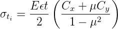
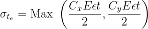
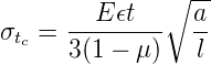
The warping stress at the interior, edge and corner regions, denoted as σti, σte, σtc in kg/cm2 respectively and given by the equation 7-8.
 | (6) |
 | (7) |
 | (8) |
where E is the modulus of elasticity of concrete in kg/cm2 (3×10⁵), ϵ is the thermal coefficient of concrete per oC (1×10⁻⁷) t is the temperature difference between the top and bottom of the slab, C x and Cy are the coefficient based on Lx∕l in the desired direction and Ly∕l right angle to the desired direction, μ is the Poisson’s ration (0.15), a is the radius of the contact area and l is the radius of the relative stiffness.
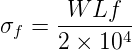
The frictional stress σf in kg/cm2 is given by the equation
 | (9) |
where W is the unit weight of concrete in kg/cm2 (2400), f is the coefficient of sub grade friction (1.5) and L is the length of the slab in meters.
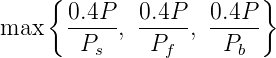
The cumulative effect of the different stress give rise to the following thee critical cases
The purpose of the expansion joint is to allow the expansion of the pavement due to rise in temperature with respect to construction temperature. The design consideration are:
The purpose of the contraction joint is to allow the contraction of the slab due to fall in slab temperature below the construction temperature. The design considerations are:
 | (10) |
where, Sc is the allowable stress in tension in cement concrete and is taken as 0.8 kg/cm2, W is the unit weight of the concrete which can be taken as 2400 kg/cm3 and f is the coefficient of sub-grade friction which can be taken as 1.5.
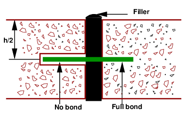
The purpose of the dowel bar is to effectively transfer the load between two concrete slabs and to keep the two slabs in same height. The dowel bars are provided in the direction of the traffic (longitudinal). The design considerations are:
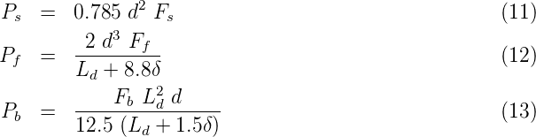
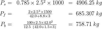
Bradbury’s analysis gives load transfer capacity of single dowel bar in shear, bending and bearing as follows:
where, P is the load transfer capacity of a single dowel bar in shear s, bending f and bearing b, d is the diameter of the bar in cm, Ld is the length of the embedment of dowel bar in cm, δ is the joint width in cm, Fs, Ff, Fb are the permissible stress in shear, bending and bearing for the dowel bar in kg/cm2.
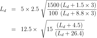
Find the length of the dowel bar embedded in slab Ld by equating Eq. 12=Eq. 13, i.e.
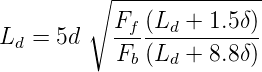 | (14) |
Find the load transfer capacities Ps, Pf, and Pb of single dowel bar with the Ld
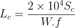
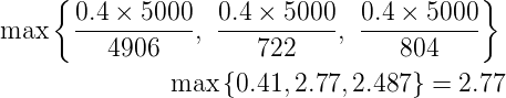
Assume load capacity of dowel bar is 40 percent wheel load, find the load capacity factor f as
 | (15) |
Spacing of the dowel bars.
Design size and spacing of dowel bars at an expansion joint of concrete pavement of thickness 25 cm. Given the radius of relative stiffness of 80 cm. design wheel load 5000 kg. Load capacity of the dowel system is 40 percent of design wheel load. Joint width is 2.0 cm and the permissible stress in shear, bending and bearing stress in dowel bars are 1000,1400 and 100 kg∕cm2 respectively.
Solution: Given, P = 5000 kg, l = 80 cm, h = 25 cm, δ = 2 cm, Fs = 1000 kg∕cm2, F f = 1400 kg∕cm2 and Fb = 100 kg∕cm2; and assume d = 2.5 cm diameter.
Step-1: length of the dowel bar Ld
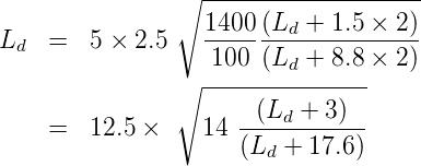
put Ld = 45.00 ⇒ Ld = 40.95
put Ld = 45.95 ⇒ Ld = 40.50
put Ld = 45.50 ⇒ Ld = 40.50
Minimum length of the dowel bar is Ld + δ = 40.5 + 2.0 = 42.5 cm, So, provide 45 cm long and
2.5 cm ϕ. Therefore Ld = 45 - 2 = 43 cm.
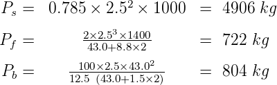
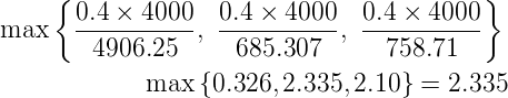
Step 2: Find the load transfer capacity of single dowel bar
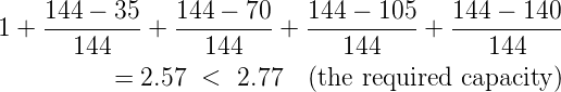
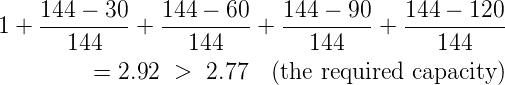
Step-3 : Find the required spacing: Effective distance of load transfer = 1.8 l = 1.8 × 80 = 144 cm. Assuming 35 cm spacing,
Actual capacity is
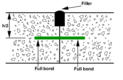
In contrast to dowel bars, tie bars are not load transfer devices, but serve as a means to tie two slabs. Hence tie bars must be deformed or hooked and must be firmly anchored into the concrete to function properly. They are smaller than dowel bars and placed at large intervals. They are provided across longitudinal joints.
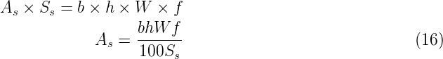
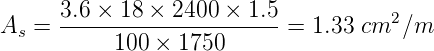
Diameter and spacing: The diameter and the spacing is first found out by equating the total sub-grade friction tot he total tensile stress for a unit length (one meter). Hence the area of steel per one meter in cm2 is given by:
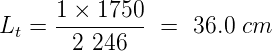
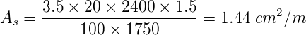
where, b is the width of the pavement panel in m, h is the depth of the pavement in cm, W is the unit weight of the concrete (assume 2400 kg∕cm2), f is the coefficient of friction (assume 1.5), and Ss is the allowable working tensile stress in steel (assume 1750 kg∕cm2). Assume 0.8 to 1.5 cm ϕ bars for the design.Length of the tie bar: Length of the tie bar is twice the length needed to develop bond stress equal to the working tensile stress and is given by:
where, d is the diameter of the bar, Ss is the allowable tensile stress in kg∕cm2, and S b is the allowable bond stress and can be assumed for plain and deformed bars respectively as 17.5 and 24.6 kg∕cm2.
A cement concrete pavement of thickness 18 cm, has two lanes of 7.2 m with a joint. Design the tie
bars.
(Solution:)
Given h=18 cm, b=7.2/2=3.6m, Ss = 1700 kg∕cm2 W = 2400 kg∕cm2 f = 1.5 S
b = 24.6 kg∕cm2.
Step 1: diameter and spacing: Get As from
 = 59 cm, say 55 cm
Design of rigid pavements is based on Westergaard’s analysis, where modulus of subgrade reaction, radius of relative stiffness, radius of wheel load distribution are used. For critical design, a combination of load stress, frictional stress and warping stress is considered. Different types of joints are required like expansion and contraction joints. Their design is also dealt with.
Given, P = 4000 kg, l = 90 cm, h = 20 cm, δ = 3 cm, Fs = 1000 kg∕cm2, Ff = 1500 kg∕cm2 and F b = 100 kg∕cm2; and assume d = 2.5 cm diameter.
Step-1: length of the dowel bar Ld,
Solving for Ld by trial and error, it is =39.5cm Minimum length of the dowel bar is Ld + δ = 39.5 + 3.0 = 42.5 cm, So, provide 45 cm long and 2.5 cm ϕ. Therefore Ld = 45 - 3 = 42 cm.
Step 2: Find the load transfer capacity of single dowel bar
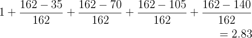
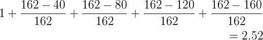
Step-3 : Find the required spacing: Effective distance of load transfer = 1.8×l = 1.8×90 = 162 cm. Assuming 35 cm spacing,
Actual capacity is
 = 54.57 cm, say 55 cm
I wish to thank several of my students and staff of NPTEL for their contribution in this lecture. I also appreciate your constructive feedback which may be sent to tvm@civil.iitb.ac.in
Prof. Tom V. Mathew
Department of Civil Engineering
Indian Institute of Technology Bombay, India
____________________________________________________________________________________________
Thu Jan 10 12:42:56 IST 2019