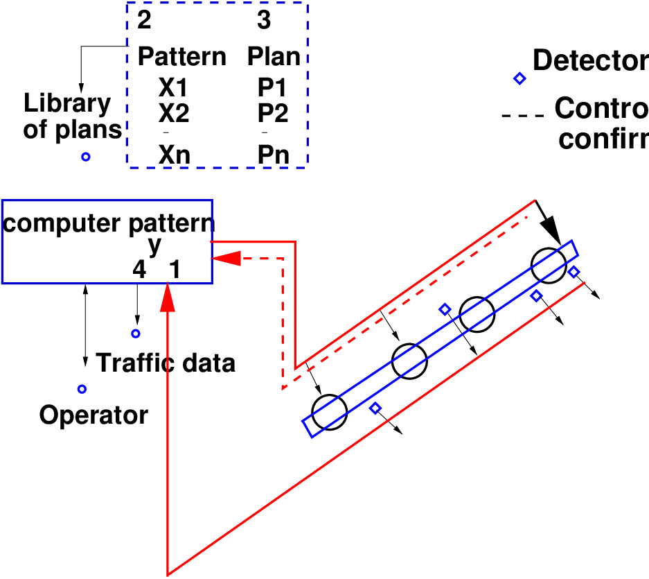
Figure 1: Computer control system with detector information used
ATC systems are intelligent real-time dynamic traffic control systems which are designed to effectively respond to rapid variations in dynamic traffic conditions. It is an advanced process to control the traffic. It is a traffic responsive system that use data from vehicle detectors and optimize traffic signal time in real time. The timing plan of traffic controllers changed automatically. The technique employs digital computers for achieving the desired objective.
The basic system Originally, it was assumed that the power of the digital computer could be used to control many traffic signals from one location, allowing the development of control plans. The basic concept can be summarized thus: the computer sends out signals along one or more arterial. There is no feedback of information from detectors in the field, and the traffic-signal plans are not responsive to actual traffic conditions. Earlier,the plans for such a system are developed based on the engineers usage of data from field studies to generate plans either by hand, or by computer,using packages available at the time. The computer solutions were then run on another machine, or in off hours on the control computer when it was not being used for control of the traffic signals. Though this “off-line” system of control plans gives an image of a deficient system, there are many advantages of this “limited” system. These include:
Collection of traffic data The ability of a computer to receive great amount of data and process it is made use of by detectors in the field for sending information back to the central location. If the information is not being used in an “online” setting and hence still does not influence the current plan selection. Typically, the computer is being used as the tool for the collection of permanent or long-term count data.
Traffic data used for plan selection
Fig. 1 shows a computer control system that actually uses the traffic data to aid in plan
selection. This can be done in one of three principal ways:
1. Use library - Monitor deviations from expected pattern: This concept uses a time-of-day
approach, looking up in a library both the expected traffic pattern and the preselected plan
matched to the pattern. The actual traffic pattern can be compared to the expected, and if a
deviation occurs, the computer can then look through its library for a closer match and use the
appropriate plan.
2. Use library - Match plan to pattern: This is a variation on the first concept, with the
observed pattern being matched to the most appropriate pre-stored pattern and the
corresponding plan being used.
3. Develop plan on-line: This concept depends on the ability to do the necessary
computations within a deadline either as a background task or on a companion computer
dedicated to such a computations. This approach presumes an advantage to tailoring the
control plan to specific traffic data.
It is necessary to note that the time between plan updates is constrained by the speed with
which the on-line plan computations can be done. The desire to have more frequent updates
implicitly assumes that the real traffic situation can be known precisely enough to differentiate
between consecutive update periods.
The various Advantages of an area traffic control system are
The various disadvantages of an area traffic control system are
Major Building blocks of the Area Traffic Control Systems are: Vehicle Detectors, Intersection Controller, Communication Network, Application Software and Central (Regional) Control System which are described below:
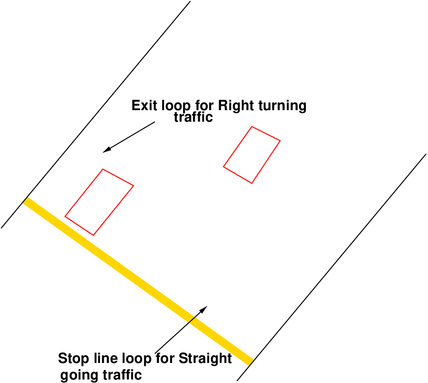
Vehicle Detectors is used to detect the presence of vehicles, to collect data to find average speed, vehicle flow, vehicle density, queue length measurement. VD acts as a nodal point between vehicle and intersection controller. Detector could be of various types example-ultrasonic, microwave radar, infrared laser radar, non-imaging passive infrared, video imaging, acoustic array, magnetic loop Inductive loop vehicle detector is commonly used. Fig. 2 is showing example of Vehicle Detectors.
In Fig. 2 two detectors are shown, 1 is for straight going traffic which will detect the vehicle which will go straight and 2 is right turning traffic which will detect the vehicle which will take right turn from there.
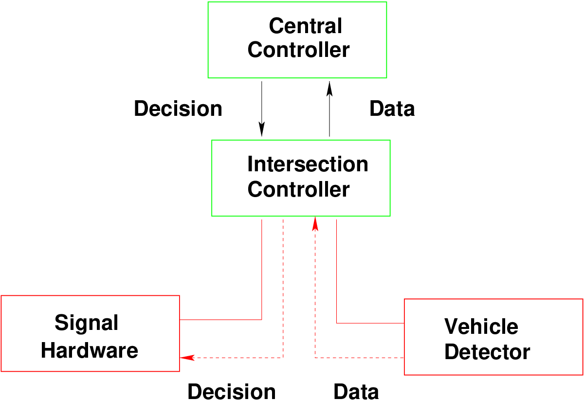
It is the micro-macro computer. It placed at intersection for temporary storage of data. It collects the data from vehicle detector and sends it to the central control. Central control processed the data and sends it back to the intersection controller which then implements the signal timings as instructed at the intersection. Intersection controller for each set of traffic signals receives the signal states from the control system.
The communication network transfers data from the signal controller, to the central control station where optimized signal timings and phases are determined and it again transfers information to the signal controller as per the data processed. It transfers the data obtained from detectors to central control which then implements the signal timings as instructed at the intersection. Fig. 3 is showing the communication network.
Application software is the software used behind the whole ATC system which performs the entire task. It is a large and complex program involving multiple systems, various procedures for implementation. Functions of Application software are: It defines the architecture flows, activities and functions and user services that planners want to deliver.
It is the main unit of ATC. In this unit collected traffic data is processed to optimize various traffic parameters like-signal timing, phase change, delay Important and major task of ATC system is performed by this unit. It supervises all the units of ATC.
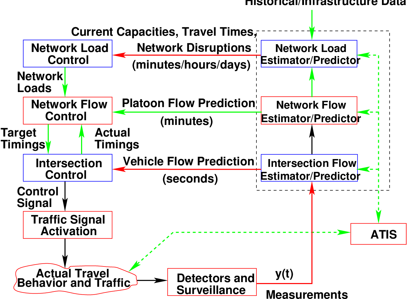
Fig. 4 is showing the arrangement of whole area traffic control system with all units of the system. These unites will be use for different-different task in the system. It could we described in three stages. At first stage estimation of is done, it is done based on the slow-varying characteristics of the network traffic load in terms of vehicle per hour than according to this estimated ATCS allow to allocate green time for each different demand for each phase. At the middle stage traffic characteristic are measured in terms of platoons of vehicle and their speeds and at last stage intersection controller select the suitable phase change based on observed and predicted arrivals of individual vehicle at each intersection.
An operating model is the abstract representation of how an System operates across process. Any system is a complex system consisting of several different interlinked logical components. An operating model breaks this complexity into its logical components in order to deliver better value. Some examples of operational models are SCOOT, SCAT and OPAC which are described below.
The Split Cycle Offset Optimization Technique (SCOOT) is an urban traffic control system developed by the Transport Research Laboratory (TRL) in collaboration with the UK traffic systems industry. It is an adaptive system which responds automatically to traffic fluctuations. Prime objective of this is to minimize the sum of the average queues in the area. It is an elastic coordination plan that can be stretched or shrunk to match the latest traffic situation. Continuously measures traffic volumes on all approaches of intersections in the network and changes the signal timings to minimize a Performance Index (PI) which is a composite measure of delay, queue length and stops in the network. Each SCOOT cell is able to control up to 60 junctions. Handling input data up to 256 vehicle counting detectors on street. Detectors are usually positioned 14 m behind the stop line.
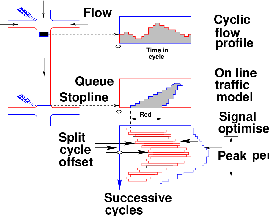
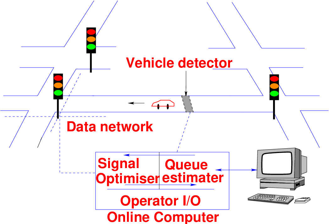
Scoot system consists of a number of SCOOT cells or computers, each cell can control up to 60 junctions and handling input data from up to 256 vehicle counting detectors on street. SCOOT detectors are placed at 14 m from the stop-line, from the approach to the junction as possible. Fig. 6 clearly shows the working principle of SCOOT where the detectors placed upstream sense the occupancy and the information is transmitted to the central computer. SCOOT traffic model and optimizers use this information to calculate signal timings to achieve the best overall compromise for coordination along all links in the SCOOT area. The main aim of the SCOOT traffic signal control system is to react to changes in observed average traffic demands by making frequent, but small, adjustments to the signal cycle time, green allocation, and offset of every controlled intersection. For each coordinated area, the system evaluates every 5 minutes, or 2.5 minutes if appropriate, whether the common cycle time in operation at all intersections within the area should be changed to keep the degree of saturation of the most heavily loaded intersection at or below 90%. In normal operation SCOOT estimates whether any advantage is to be gained by altering the timings. Fig. 6 is showing the working principle of SCOOT.
From above fig we can have an idea that vehicle will be detected with the help of vehicle detector. The collected data will be send to intersection controller after that it will be send to the central controller with the help of communication network. There it will be use to estimate the signal timing according to the actual traffic flow needs. Then the central controller will send the signal timing to the intersection controller to implement.
SCAT (Sydney Co-ordinated Adaptive Traffic Control) System was developed by the Roads and Traffic Authority (RTA) of New South Wales, Australia in the late 1970s. It is automated, real time, traffic responsive signal control strategy. Timing of signals is governed by computer-based control logic. It has ability to modify signal timings on a cycle-by-cycle basis using traffic flow information collected at the intersection approach stop lines. It is not model based but has a library of plans that it selects from and therefore banks extensively on available traffic data.
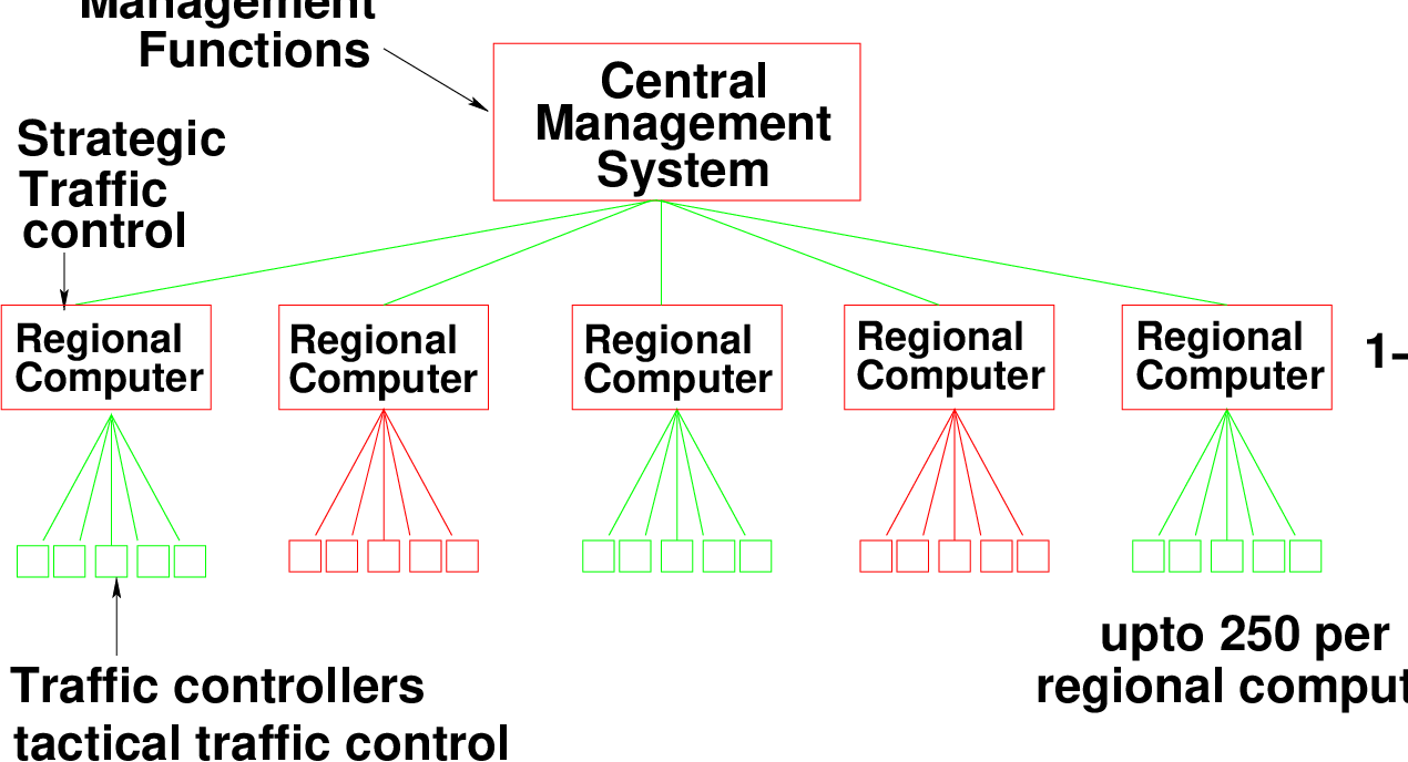
The system is very flexible, powerful, expandable, and yields unprecedented monitoring and management possibilities. The total system is divided into intersection, regional and a central system management. Distribution of the regional computers is determined by the economics of communication. Each regional computer maintains autonomous control of its region. Input data is collected by a system of traffic sensors. Sensors may be inductive loop detectors embedded in the pavement or video image devices mounted overhead on the signal strain poles. The system is designed to auto calibrate itself according to the data received, to minimize the need for manual calibration and adjustment. Fig. 7 shows the SCAT Computer Hierarchy.
It is developed by Parsons Brinkerhoff Farradyne Inc. and the University of Massachusetts at Lowell jointly. It is a distributed traffic signal control strategy. The network is divided into sub-networks, which are considered independently for optimization purpose. OPAC breaks between two models: one for congested networks and the other for uncongested networks.
Area traffic control system can reduce traffic delays, fuel consumption, accident, congestion, travel time, environmental pollution substantially and can increase average flow speed. Regarding ATC systems, SCOOT, SCAT and OPAC are popular in advanced countries but such systems cannot cope up with Indian situations because in India traffic is not lane following, highly mixed traffic, uncontrolled side road and on-street parking, Data loss due to power failure and Availability of funds.
I wish to thank several of my students and staff of NPTEL for their contribution in this lecture. I wish to thank specially my student Mr. Hemendra Jatav for his assistance in developing the lecture note, and my staff Ms. Reeba in typesetting the materials. I also appreciate your constructive feedback which may be sent to tvm@civil.iitb.ac.in
Prof. Tom V. Mathew
Department of Civil Engineering
Indian Institute of Technology Bombay, India
_________________________________________________________________________
Thursday 28 September 2023 10:47:58 AM IST