Non-intrusive technologies include video data collection, passive or active infrared detectors, microwave
radar detectors, ultrasonic detectors, passive acoustic detectors, laser detectors and aerial photography. All
these technologies represent emergent fields that are expanding rapidly with continuing advances in signal
processing. At present time such technologies are used to provide supplemental information for
selected locations or for specific applications (e.g., queue detection at traffic signals). Most
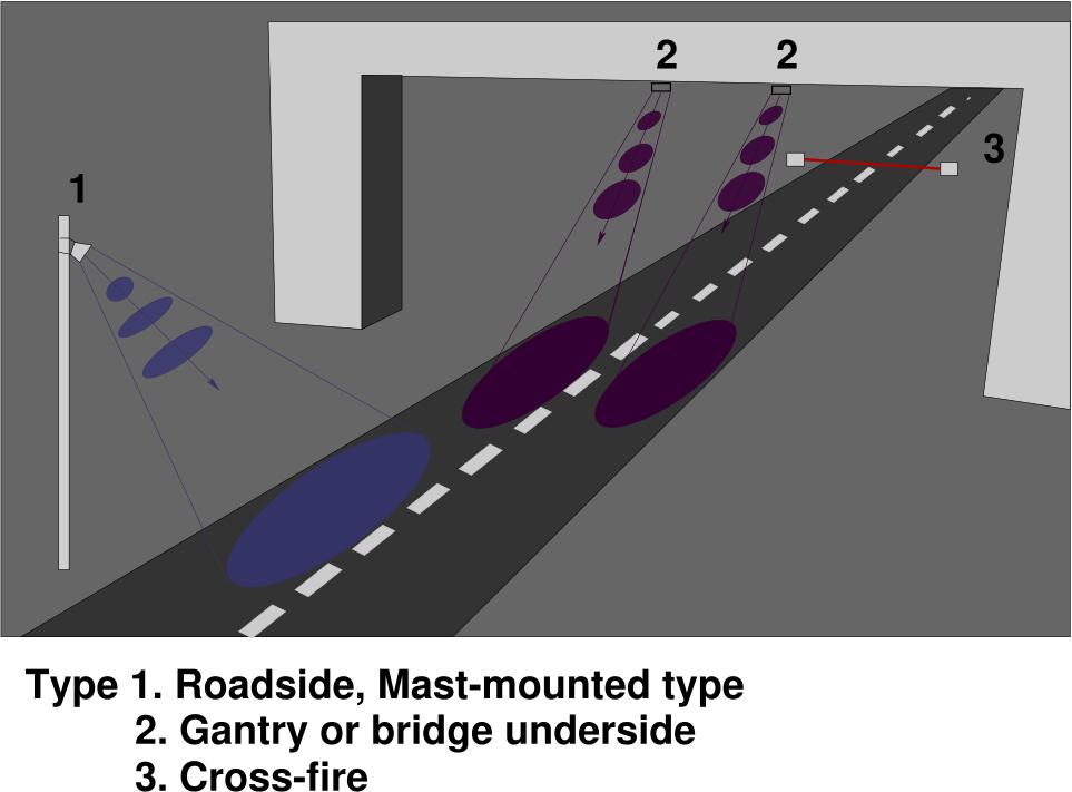
non-intrusive systems are operationally and somewhat visually similar, consisting of small
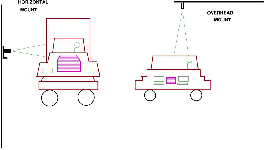
electronics unit mounted in a weatherproof housing placed in various locations, as shown in Fig. 1.
The first type of non-invasive detectors are roadside mast-mounted. The detector possesses a
field-of-regard covering an oblique area upstream or downstream of the unit. There are also
multiple zones of detection defined within the overall field of regard, or the overall zone of
detection same as the field of regard, depending on the specific detector type and technology.
Obscuration problems occur when high-sided vehicles screens lower vehicles from the detector or
the field-of-view being too large, leading to detection of vehicles outside the desired lane.
The second type of non-invasive detectors are mounted on gantries or bridge undersides, with field of regard directly below, or at a slight oblique to the unit. Finally, some units, such as open-path pollutant monitors are mounted road side at ground level, firing a beam across the road. Such units are subject to side-by-side masking and hence most suitable for only single lane, unidirectional flows.
The traffic parameters are collected by frame-by-frame analysis of video images captured by roadside
cameras. The following parameters are collected: Depending on the processing methodology
almost all traffic parameters are captured from video analysis. Simple video systems often
collect flow volume and occupancy. More complex systems allow the extraction of further
parameters.
Advantages
Possibility to capture all desired traffic information, including some parameters that are not readily
obtainable using other types of detectors Possibility of a permanent visual record of the traffic flow that
reviewed and analyzed by a human operator.
Disadvantages
VID systems are susceptible to obscure issues, as with other non-intrusive detectors. Performance of VID
systems might be degraded in bad weather or low light conditions.
System Design
System design consist of following four stages, construction of background image, detection
of frame features, matching of detected frame features and refining matched vehicle features.
Creating a background image (an image representing the scene without moving vehicles)
using a computer is a difficult task. The reason is that a computer, unlike humans, is unable
to distinguish background and vehicles by considering a single image. The number of frames
improves the quality of background images, it increases the time consumed in creating them.
This is caused by the large number of mathematical instructions required to construct a
background image.
In the second stage it analyzes each frame in the sequence and detects features that
correspond to moving vehicles in the scene. Depending on the method used, several types
of features can be highlighted to represent moving vehicles. In the second stage apply
background subtraction on each frame to remove the static background of the scene. The
resulting image consists of blobs (collections of pixels with non-zero values) corresponding to
moving vehicles. These blobs are enhanced by processing further and detected as the main
feature. Several attributes about the blobs are recorded in memory for processing in the
coming stages.
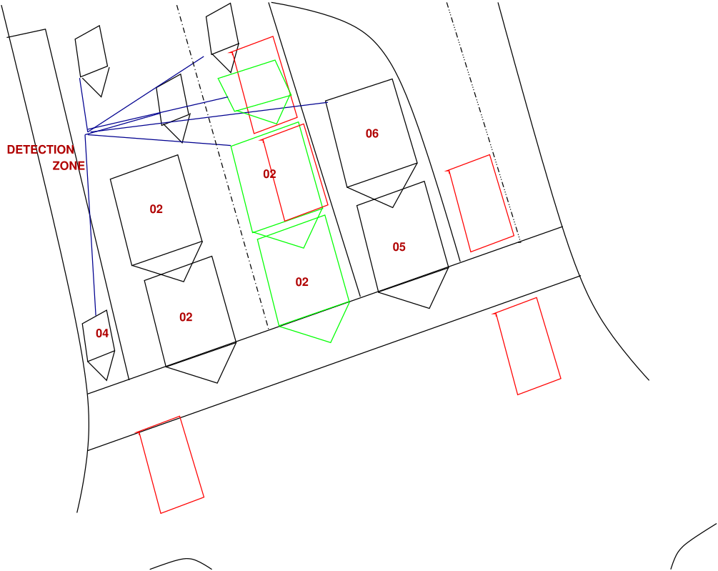
Also, there are false blobs, not corresponding to any moving object. Such blobs are present because of excessive noise in the image or poor quality of the background image. Such features need not be processed further for estimating traffic flow. Therefore, these features are identified from the input features and discarded. Now, the remaining features can be considered as vehicle features. In third stage by matching the features detected in previous frames with those from the current frame, vehicles can be tracked. In the final stage matched vehicle features can be refined to correct features in the frames. However, this is a complex task, as most of the information in the image has been lost after labeling. Therefore, it is necessary to extract information from original frames to perform this task. All these system design process are done by different algorithms.
The sensors are mounted overhead to view approaching or departing traffic or traffic from a side-looking configuration. Infrared sensors are used for signal control; volume, speed, and class measurement, as well as detecting pedestrians in crosswalks. With infrared sensors, the word detector takes on another meaning, namely the light-sensitive element that converts the reflected or emitted energy into electrical signals. Real-time signal processing is used to analyze the received signals for the presence of a vehicle.
Passive Infrared (PIR)
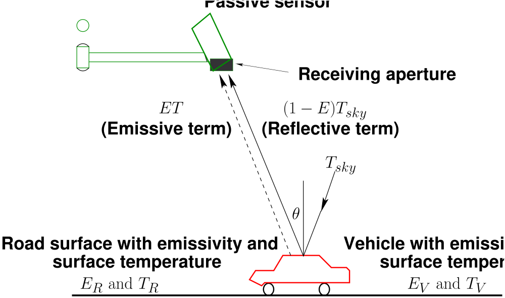
Detection of vehicle based on emission or reflection of infrared (electromagnetic radiation of
frequency \(10^{11} - 10^{14} Hz\)) radiation from vehicle surface, as compared to ambient levels emitted or reflected
from the road surface shown in Fig. 3. The PIR system collected following parameters:
Flow volume, Vehicle presence, and detection zone occupancy. Speed with unit with multiple
detection zones.
Advantages
Disadvantages
Active Infrared (AIR)/Laser
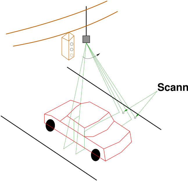
Low power LED or laser diode fires a pulsed or continuous beam down to road surface as shown in
Fig. 4. Time for reflection to return is measured. Presence of a vehicle lowers the time of reflection.
High scanning rates provides a detailed profile for classification determination. Use of Doppler
frequency shift from moving object allows for very accurate speed determination. The AIR system
collected following parameters flow volume, speed, classification, vehicle presence, traffic
density.
Advantages
Disadvantages
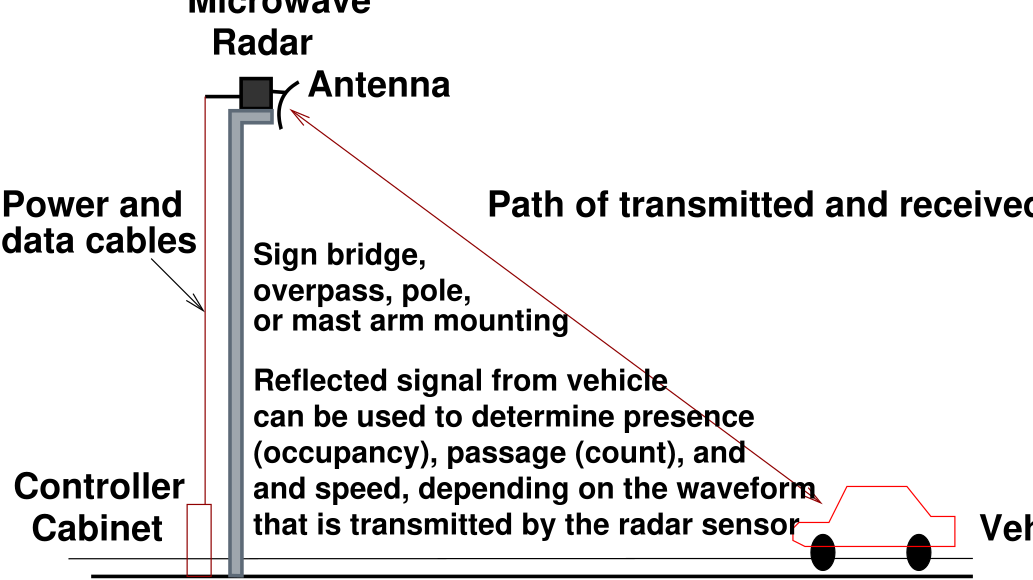
Low energy microwave radiation (2.5 to 24 GHz) is transmitted into the detection zone. Objects within
the zone reflect a portion of the radiation back to a receiver. Doppler units use the frequency shift of the
return to calculate speed as shown in Fig. 5. It can’t detect the stationary objects. The microwave system
collected following parameters.
Doppler - Flow volume and speed;
Frequency-Modulated, Continuous Wave (FMCW) - Flow volume, speed and presence;
Microwave - Flow volume, speed, presence, possibly classification;
Advantages
Disadvantages
Ultrasonic sensors transmit pressure waves of sound energy at a frequency between 25 and 50 KHz. Pulse
waveforms measure distances to the road surface and vehicle surface by detecting the portion of the
transmitted energy that is reflected towards the sensor from an area defined by the transmitter’s beam
width. When a distance other than that to the background road surface is measured, the sensor interprets
that measurement as the presence of a vehicle as shown in Fig. 6. The received ultrasonic energy
is converted into electrical energy that is analyzed by signal processing electronics that is
either collocated with the transducer or placed in a roadside controller. Vehicles flow and
vehicular speed can be calculated by recording the time at which the vehicle crosses each
beam.
Advantages
Disadvantages
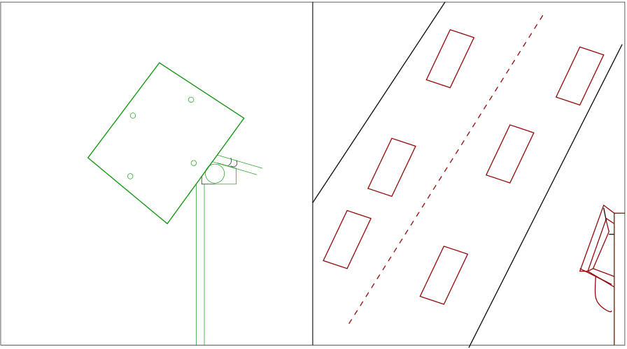
An array of microphones is used to detect the sound of an approaching vehicle above an ambient threshold
level. Time lags and signal variations between microphone positions are used to determine vehicle
location relative to the array as shown in Fig. 7. Further processing of signal yield to speed
information and possibly engine type classification. It collected flow, speed, occupancy, possibly
classification.
Advantages
Disadvantages
A non- Intrusive technology is very effective compared to the Intrusive technologies.
I wish to thank several of my students and staff of NPTEL for their contribution in this lecture. Specially, I wish to thank my student K. B. Raghuram for his assistance in developing the lecture note, and my staff Ms. Reeba in typesetting the materials. I also appreciate your constructive feedback which may be sent to tvm@civil.iitb.ac.in. Prof. Tom V. Mathew, Department of Civil engineering, Indian Instiute of Technology Bombay, India.