One of the most effective and efficient methods of controlling the traffic on a highway is the adoption of
high intersection geometric design standards. Channelization is an integral part of at grade intersections
and is used to separate turning movements from through movements where this is considered advisable
and hence helps reduce the intensity and frequency of loss of life and property due to accidents to a large
extent. Proper Channelization increases capacity, improves safety, provides maximum convenience, and
instils driver confidence. Improper Channelization has the opposite effect and may be worse than none
at all. Over Channelization should be avoided because it could create confusion and worsen
operations.
2 Definitions and Important Terms
Channelization - It is the separation or regulation of conflicting traffic movements into
definite paths of travel by traffic islands or pavement marking to facilitate the safe and orderly
movements of both vehicles and pedestrians.
Conflict - It is defined as the demand for the same highway space by two or more users of the
highway. Conflicts are classified into mainly three types:
Crossing conflicts
Diverging conflicts
Merging conflicts
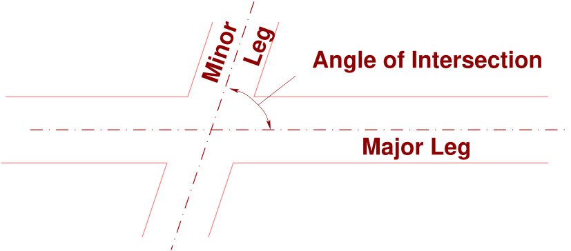
Angle of Intersection - The angle of intersection is that formed by the centerlines of
the intersecting streets. Where the angle of intersection departs significantly (more than
approximately \(20^o\)) from right angles, the intersection is referred to as a skewed intersection.
Fig. 1 shows the angle made between the center lines of the major and minor legs.
Figure 1: Angle of Intersection
Refuge Areas - The area which is used to give refuge to the pedestrians crossing a street (the
open area between two medians) is known as a refuge area.
3 Objectives
The use of Channelization is often creative and innovative, providing for vehicle path separation and
distinct and thus in general making traffic flow safer, smoother, simpler and efficient. The main objectives
of Channelization can be summarized as follows:
Separation of maneuver areas: The drivers should be presented with only one decision at
a time to reduce confusion and the influence of operations caused due to the overlapping of
maneuver areas.
Reduce excessively large paved areas: The spread of the paved area can be considerably
reduced by the construction of raised islands and medians where these are considered safe
and necessary.
Control of maneuver angle:The intensity of accidents can be reduced to a large extent
by providing small angles for merging, diverging and weaving (at low relative speeds) and
approximately right angles for crossing (at high relative speeds). The maneuver angle can be
easily controlled by constructing islands of appropriate shapes and sizes.
Favor predominant turning movements: Channelization is also directed for giving
preference to turning movements at an intersection where the proportion of such traffic is
high.
Control of speed: Channelization is also used for supporting stop or speed regulations by
removing differentials in speed for merging, diverging, weaving and crossing by using the
bending and funneling techniques.
Protection and storage of turning and crossing vehicles: To shadow slow or stopped
vehicles from other traffic flows.
Blockage of prohibited movements: Proper Channelization also helps maintain traffic
regulations by making prohibited movements impossible or inconvenient.
Provide space for traffic control devices: To provide space for traffic control devices
when the ideal location for the same is within the intersection area.
Segregation of non-homogeneous flows: Channelization provides separate channels for
turning and through, fast and slow, and opposite direction traffic.
Protection of pedestrians and reduction of crossing distances between refuses:
Non-traversable and wide medians provide a refuge for pedestrians crossing a street.
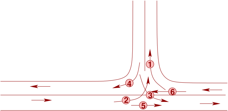
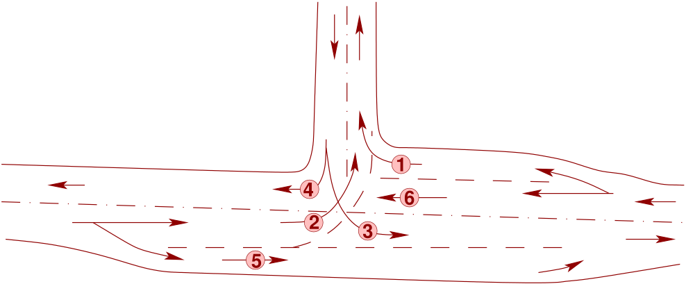
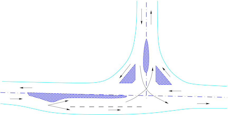
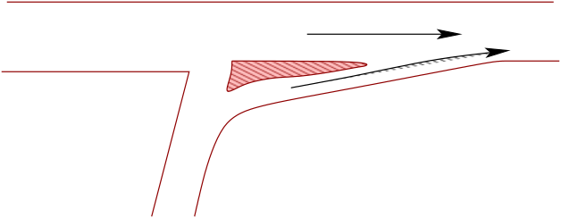
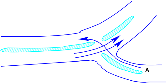
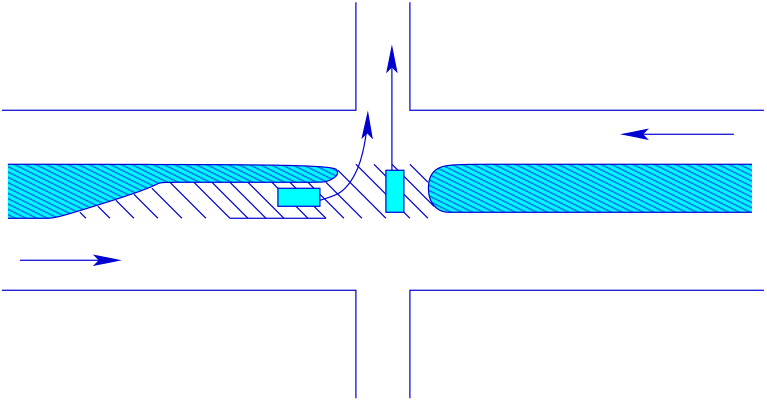
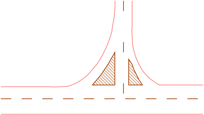
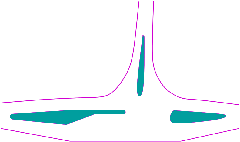
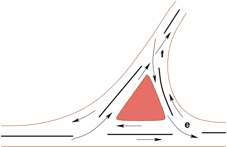
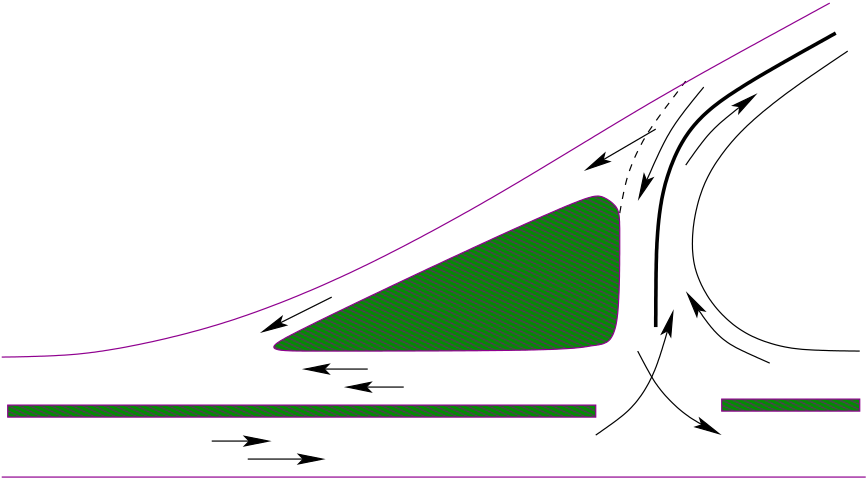
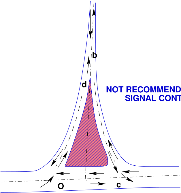
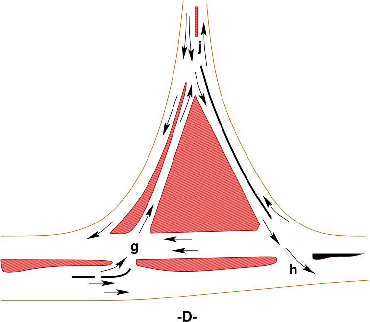
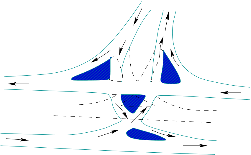
Consider for example the T-intersection shown in Figs. 2, 3, and 4. In Fig. 2, the intersection
has no special Channelization for helping drivers in avoiding conflicts between movements. In
Fig. 3, a passing lane for through vehicles in the eastbound direction and a westbound right-turn
lane has been added, which helps in separating the turning traffic from the through ones.
In Fig. 4, the use of lanes is further clarified due to the addition of channelizing islands.
Figure 2: Illustration of T-intersection Channelization, (a)Intersection with no Channelization
Figure 3: Illustration of T-intersection Channelization, (b)Intersection with right-turn and passing
lane
Figure 4: Illustration of T-intersection Channelization, (c)Fully channelized intersection
4 Design Principles
Design of a channelized intersection usually involves the following significant controls: the type of design
vehicle, the cross sections on the crossroads, the projected traffic volumes in relation to capacity, the
number of pedestrians, the speed of vehicles, and the type and location of traffic control devices.
Furthermore, the physical controls such as right-of-way and terrain have an effect on the extent of
Channelization that is economically feasible. The degree to which each of these principles applies will depend upon the features mentioned above. While
a principle may be modified in its application to a particular site, disregard of these may result in a
hazardous design. The principles may be summarized as follows:
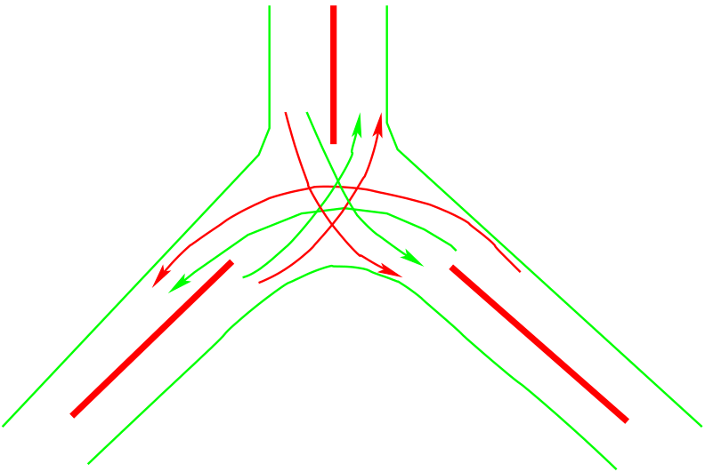
Reduction of the Area of Conflict: The impact area is decreased when
Channelization is provided, and hence the probability of conflicts is also
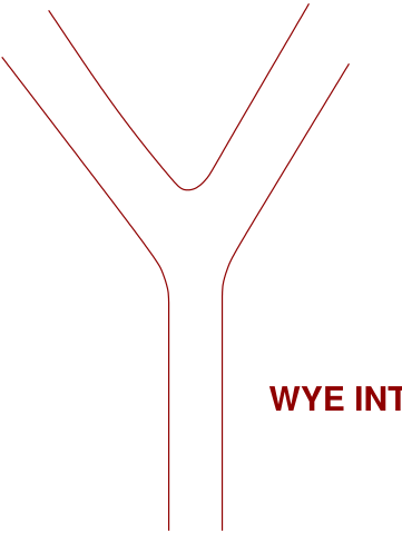
reduced. The figure below further clarifies the statement. Fig. 5 shows the
conflict area in a Y-intersection without Channelization and Fig. 6 shows
the reduced conflict area in the same intersection after providing medians.
Figure 5: Conflict area in all paved intersection
Figure 6: Conflict area in a channelized intersection
Merging traffic streams at small angles: Merging at small angles permits the flow of
traffic streams with minimum speed differentials. Hence, the gap acceptance time is also
small in such cases. The merging of roadways should be done as shown below in Fig. 7.
Figure 7: Merging of traffic streams
Reduction of the speed of incoming traffic by bending its path: The
speed of vehicles entering into the intersection can be reduced by bending the path
to the intersection approach. However as far as possible the path of the major
traffic stream should not be bent. The above technique is shown below in Fig. 8.
Figure 8: Bending path of incoming minor street
Reduction of speed of traffic by funneling: The funneling technique can also be
used for reducing the speeds of the incoming vehicles. Due to the decrease in the width
of the lane at the approach, the drivers tend to reduce the speed of their vehicles
near the intersection. Fig. 9 shows the funneling technique used for reduction of speed.
Figure 9: Reduction of speed by funneling
Protection for turning vehicles/crossing conflicting traffic streams:
Provision of a refuge area between the two opposing streams allows the driver
of a crossing vehicle to select a safe gap in one stream at a time and also
provides a safer crossing maneuver. Fig. 10further clarifies the above statement.
Figure 10: Refuge area for protecting crossing or turning traffic
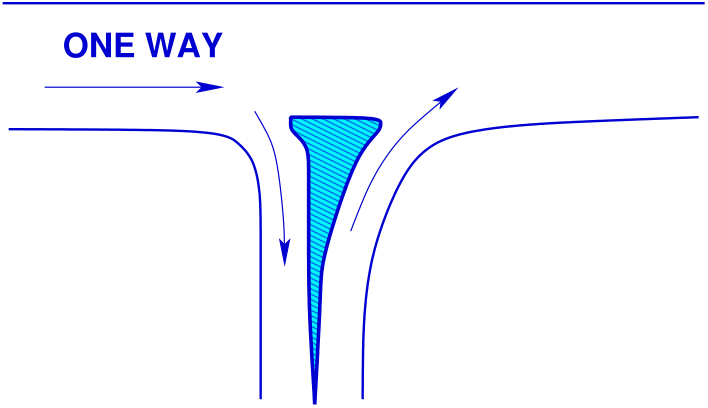
Discourage prohibited turns by island placement and shape:
Undesirable and prohibited turns can be discouraged by the proper selection
of shape and location of the islands. Fig. 11 shows how prohibited
turns can be discouraged by proper shaping and placement of islands.
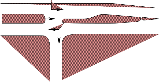
Providing locations of traffic control devices: Channelization may provide locations for
the installation of essential traffic control devices, such as stop and directional signs, signals
etc. Fig. 12 shows how channelizing devices can also be used for locating traffic control devices.
Figure 12: Location of signal posts on medians at intersections
5 Channelizing devices
A channelizing device can be defined as any structure which helps in providing Channelization. These can
be wide raised medians, non-traversable road islands, traversable raised curbs or even flush channelizing
devices. A brief description of the various devices which are used for the purpose of Channelization are
given in the following sections.
Wide Raised Medians In this form of channelizing device, a raised wide separator is constructed between the
two opposing lanes and the space on the separator (median) is used either for planting
some trees and/or for providing space for traffic signs etc. Fig. 13 shows a typical wide
raised median on a freeway. A median varying between 1.2 m and 30 m in width may
be employed. The higher values of width are adopted on freeways, where sufficient space
is available for the construction of these. In addition, a well-landscaped wide median
will also provide aesthetic benefits to the surrounding neighborhood. A wide median,
if attractively landscaped, is often the most aesthetically pleasing separation method.
Figure 13: Wide raised median
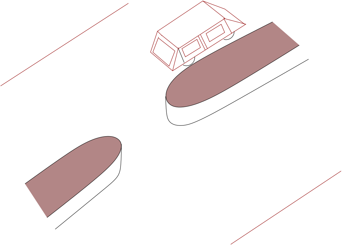
Non- traversable Raised Islands In this type of device, a narrower and a higher median than the traversable island is
constructed between the opposing lanes. This class of device has the advantage of a narrower
median, but its use should be restricted to approach roadways with vehicle speeds of 60
kmph or below. These are generally 15 to 20 cm high and about 60 cm in width. Due to
the height, most of the vehicles are not able to cross the median, and hence the name.
Fig. 14 shows a non-traversable raised island constructed on a roadway. These devices are
substantial enough that each installation should be carefully designed, as an inappropriately
placed median can constitute a hazard if struck by an errant vehicle and hence the severity
and crash risk is highly increased on the roadways having non-traversable raised islands.
Figure 14: Non-traversable Raised Island (source: [13])
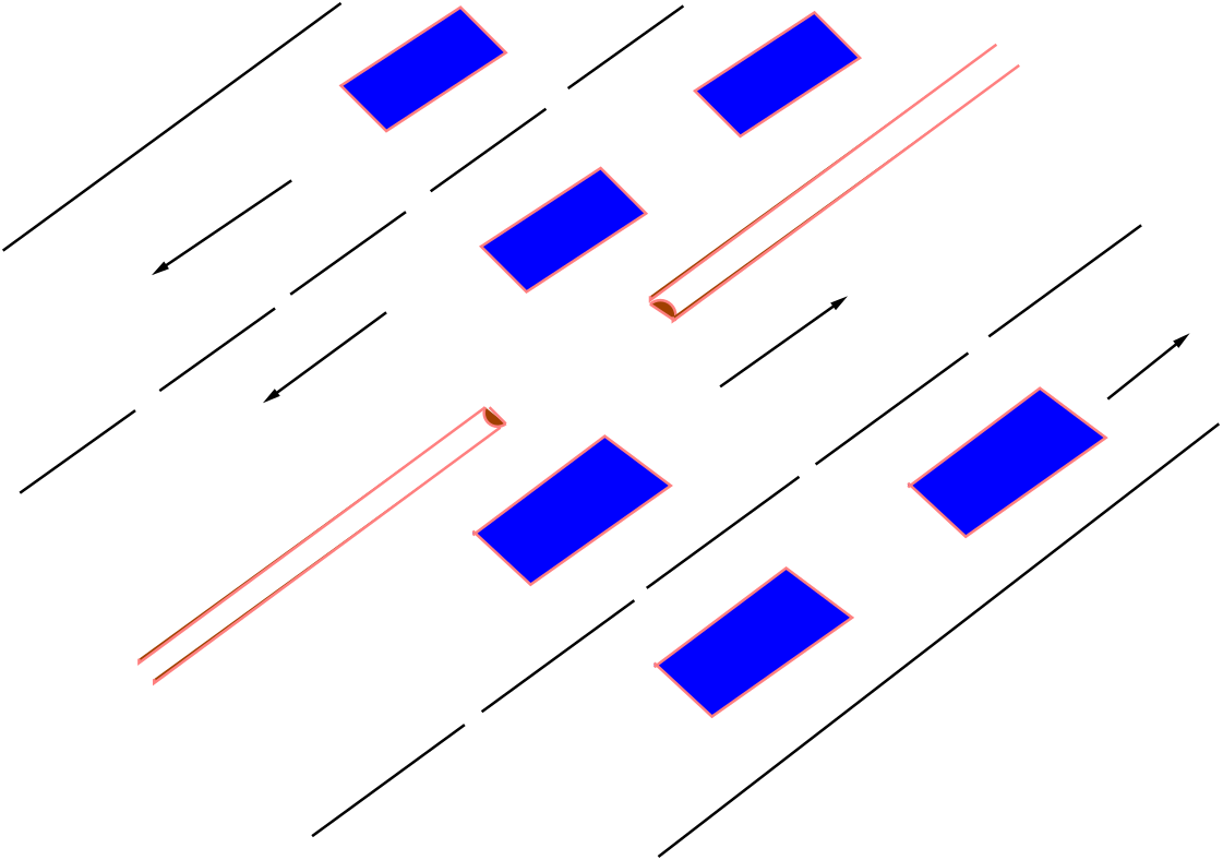
Traversable Raised Curb Systems In this device, a narrow and mountable type of raised curb is constructed to separate the
traffic moving in the opposing lanes. This class of channelizing device is the narrowest, and
therefore the easiest to fit in a wide range of roadway cross-section widths. The curb is up to
10 cm in height and up to about 30 cm in width. Curbs are formed with a rounded shape that
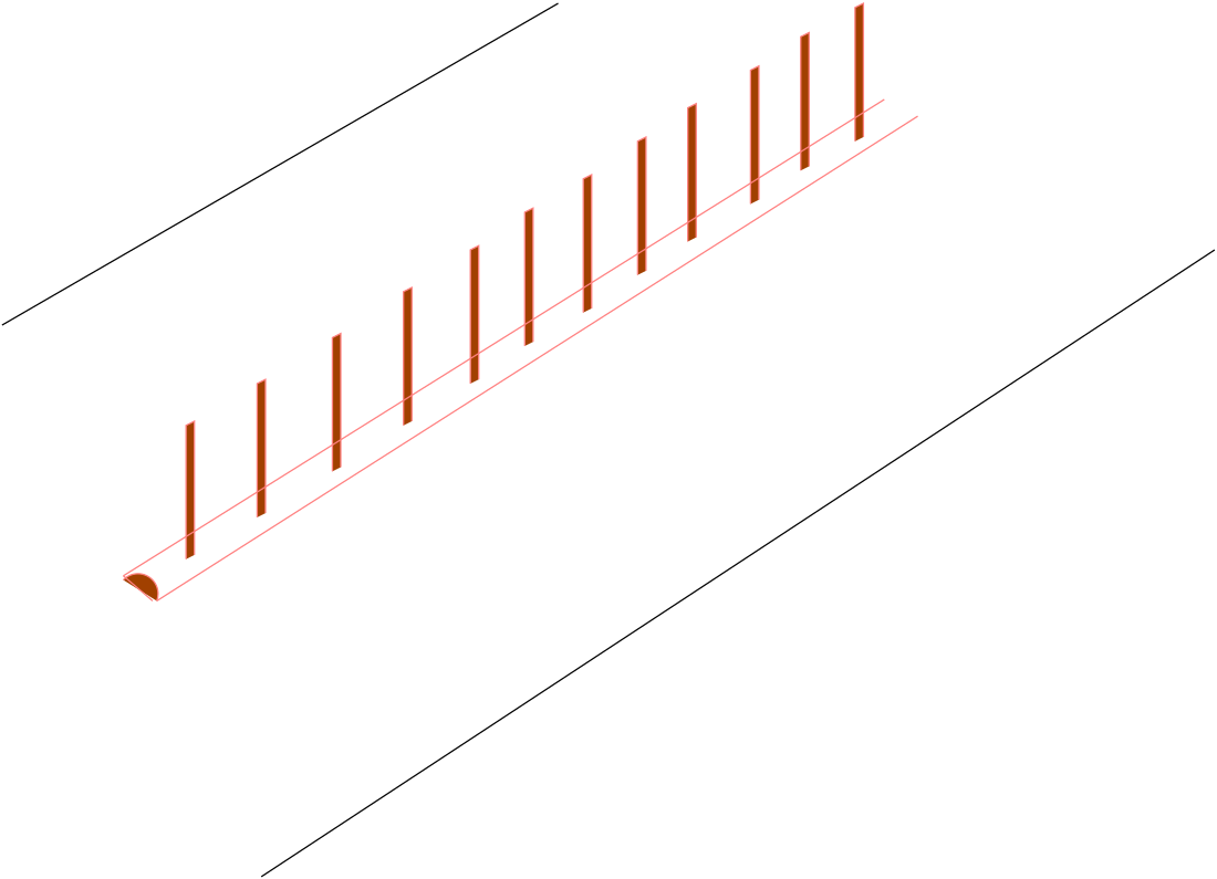
will create minimal vehicle deflection upon impact. Generally, it is used with reboundable,
reflectorized vertical panels to provide a visual deterrent to the drivers to cross over to
opposite traffic lane. The main advantage of this type of device is that it can be installed on
existing roadway centerlines, without the need for widening the roadway approaches to the
crossing. Figs. 15 and 16 shows traversable raised curbs with and without vertical panels.
Figure 15: Traversable Raised Curb System (without vertical panels)
Figure 16: Traversable Raised Curb System (with vertical panels)
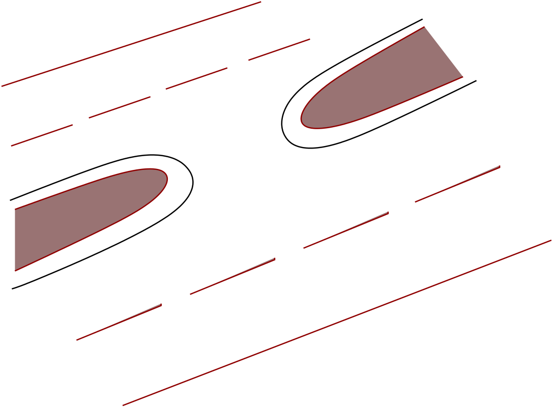
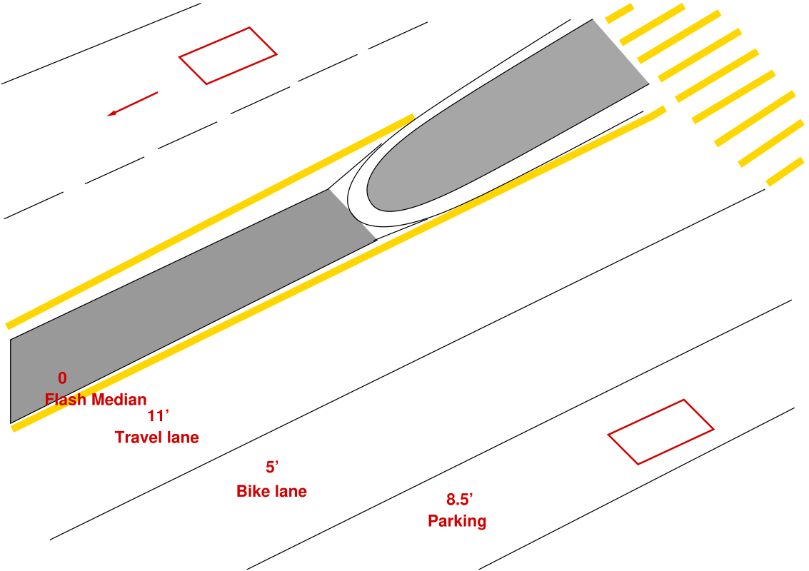
Flush Channelization In this type of Channelization, a variety of treatments, including raising them above
the pavement just slightly (2 to 5 cm); the application of pavement markings and
other types of contrasting surfaces etc are possible. These may also be unpaved
where they are formed by the pavement edges of existing roadways. In areas
where snow plowing may be necessary, flush islands are the preferred design.
Fig. 17 below shows how flush islands can also be used for achieving channelizing
objectives. The area seen flushed with the road surface in Fig. 17 is the flush island.
Figure 17: Flush island providing Channelization objectives
6 Traffic Islands
A principle concern in Channelization is the design of the islands. An island is a defined area between
traffic lanes for control of vehicle movements. Within an intersection area, a median or an outer separation
is considered to be an island. It may range from an area delineated by barrier curbs to a pavement area
marked by paint.
6.1 Classification of Islands
Traffic islands usually serve more than one function, but may be generally classified in three separate
types:
Channelizing Islands - These are designed to control and direct traffic
movement, usually turning. Channelizing islands are are shown in Fig. 18.
Figure 18: Channelizing Islands
Divisional Islands - These are designed to divide opposing or same direction traffic streams,
usually through movements. Fig. 19 shows the placing of divisional islands in a roadway.
Figure 19: Divisional Islands
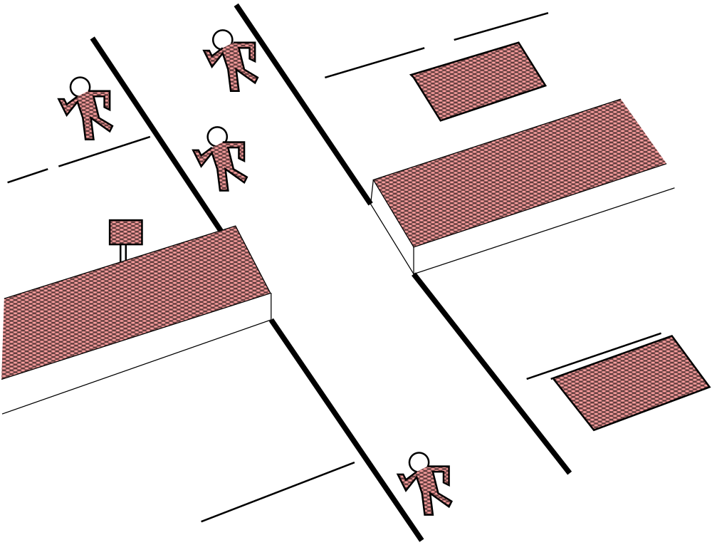
Refuge islands - Pedestrian islands are provided to serve as safety zones
for the aid and protection of persons on foot. If a divisional island is located
in an urban area where pedestrians are present, portions of each island can
be considered a refuge island. Refuge islands are shown below I Fig. 20.
Figure 20: Refuge Islands
The design aspects of the traffic islands are dealt in detail in the following sections.
6.2 Design Considerations for Traffic Islands
The necessity for an island should be determined only by careful study, since it is placed in an area that
would otherwise be available for vehicular traffic. The island design should be carefully planned so that the
shape of the island will conform to natural vehicular paths and so that a raised island will not constitute a
hazard in the roadway. A judiciously placed island at an intersection on a wide street may eliminate the
need for traffic signal control by channelizing traffic into orderly movements. The total design of traffic
islands can be studied in three steps:
Selection of appropriate island type (barrier, mountable, painted or flush): The
site and traffic conditions in each intersection are different and hence the island type suitable
for each requires separate attention. The traffic island selected may vary from barrier type
islands to flush islands marked on the roadway surface.
Determination of shape and size of islands: The shape of the island and its size in
an intersection depends on the geometry and space availability at the same. A proper shape
and size of the island (in case of raised islands) must be selected so that it is able to both
channelized the traffic and not pose any type of hazard.
Location relative to adjacent traffic lanes: The islands must be offset from the roadway
by some distance to remove the risk of a vehicle dashing against the same. The width of offset
is maximum at the entry of the island and decreases gradually as one moves towards the end
of it.
6.3 Guidelines for selection of island type
As mentioned earlier, each intersection has a unique geometry and flow values, and hence needs special
attention as far as the use of Channelization devices are concerned. The main factors affecting the
selection of the island type are:
Traffic characteristics at the intersection
Cost considerations, and
Maintenance needs
The raised islands and flush Channelization are dealt with in details in the following sections.
6.3.1 Flush Channelization
Flush Channelization is usually appropriate in the following conditions:
On high speed rural highways to separate turning lanes.
In constrained locations, i.e. the locations where vehicle path definition is desired but space
for raised islands not available.
For separating opposing traffic streams of low speed streets.
In areas where frequent removal of snowfall is required, i.e. in places of high snow fall.
It can also be used as a temporary Channelization either during construction or to test traffic
operations prior to the actual installation of raised islands.
However, the main demerits of this type of Channelization are :
It is not effective in prohibiting or preventing traffic movements.
It is also not appropriate for islands intended to serve as pedestrian refuge.
6.3.2 Raised Islands
The locations where the construction of raised islands assumes importance are:
The primary function of the channelizing device is shielding pedestrians or to provide refuge
to pedestrians crossing a street.
Also, the primary/secondary function is locating traffic signals or other fixed objects.
Intention is to prohibit or prevent certain traffic movements.
To separate high volume opposing traffic flows.
The raised islands are also particularly important at intersections with unusual geometry i.e.
skewed intersections.
A comparison between the usefulness and the operating conditions of the two types of Channelization is
presented in Table. 1.
Table 1: Flush Channelization vs Raised Channelization
FLUSH CHANNELIZATION
OPERATING CONDITIONS
1. For Right turns
High Speeds
2. To provide temporary or trail Channelization
Rural highway
3. To shadow left turns
Minor urban intersections
RAISED CHANNELIZATION
OPERATING CONDITIONS
1. Post signs or signals
Urban streets
2. Provide pedestrian refuse
Low speeds
3. Prevent wrong way movements
High volumes
6.4 Guidelines for design of Traffic Islands
The main design principles followed for the design of the shape and size and shape of the traffic island are
as follows:
Shape and size: Islands are generally either narrow and elongated or triangular in shape,
are normally situated in areas of the roadway outside the planned vehicle paths, and are
shaped and dimensioned as component parts of the street or intersection layout. The actual
size differs as governed by site conditions, but the following minimum size requirements should
be met to insure that the island will be large enough to command attention.
Traffic lanes or turning roadways should appear natural and convenient to their intended
users.
Number of islands should be held to a practical minimum to avoid confusion.
The islands should be large enough to be effective. Small islands do not serve as channelizing
devices and pose maintenance problems.
These should not be introduced at locations with restricted sight distance or middle of sharp
horizontal curves due to sight distance considerations.
Table. 2 gives the recommended minimum and desired area values of the traffic islands in typical urban and
rural intersections.
Table 2: Recommended Island Sizes
Location of Intersection
Size(Sq.meters)
Minimum
Desired
Urban
4.65
7
Rural and High Speed urban/Suburban
7
9.3
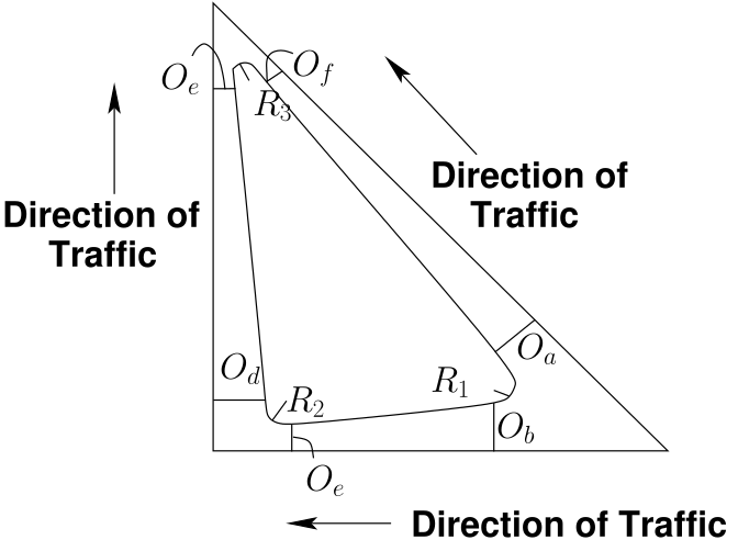
6.5 Guidelines for providing offset to the traffic islands from the road edge
The orientation of islands near intersections is dictated by the alignment of the intersecting
roadways and their associated travel paths. Proper island design must minimize the potential for
vehicle impacts and reduce their severity. This is most often accomplished by offsetting the
approach ends of islands from the edge of travel lane them, tapering them inward. Another
technique that is the use of rounded approach noses that may also be sloped downward on their
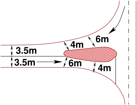
approach ends. The general design dimensions of corner islands for roadways in shown in Fig. 21.
Figure 21: Recommended Offset Dimensions for location of Traffic Islands
Another design consideration for islands is their surface finishing. Islands may be paved or landscaped.
Though paved islands are easier to maintain, yet they are typically not as aesthetically pleasing. The use
of colors that have contrast with the pavement surface is desirable because they allow the
island to be more clearly seen by drivers. Normally concrete islands are paired with asphalt
roadways and vice versa. Brick paver are also used in areas where aesthetics are important. Other
concerns include the need to provide adequate slope to the surface of the island to facilitate
drainage and to keep the island free of sight obstructions and collision. Thus, all landscaping
features should be kept below the clear vision envelop and should not incorporate other fixed
hazards.
6.5.1 Curve/taper combinations for turning roadways and islands
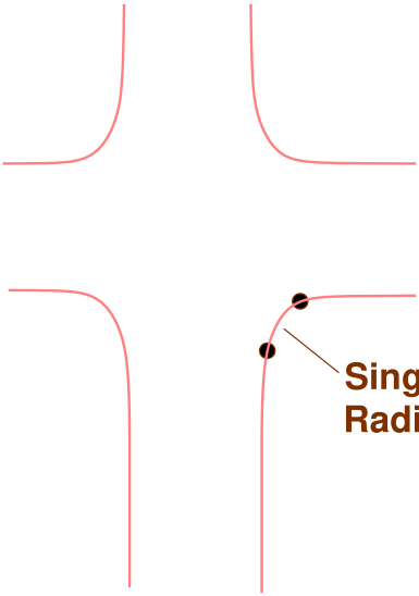
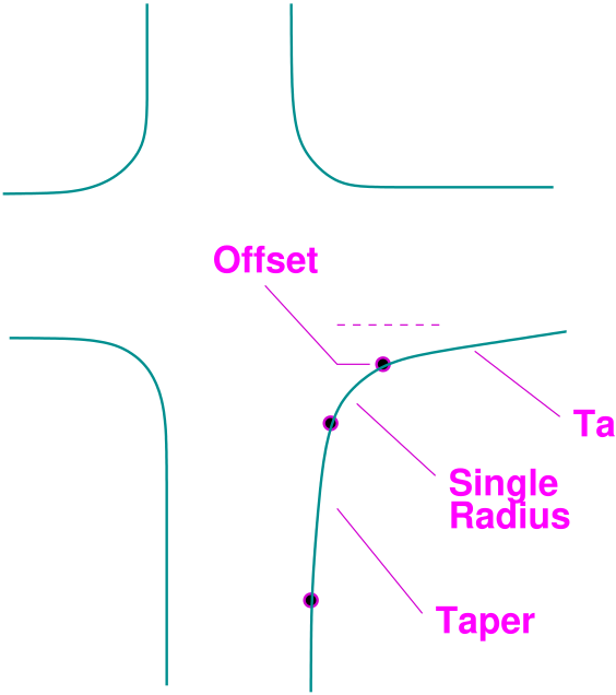
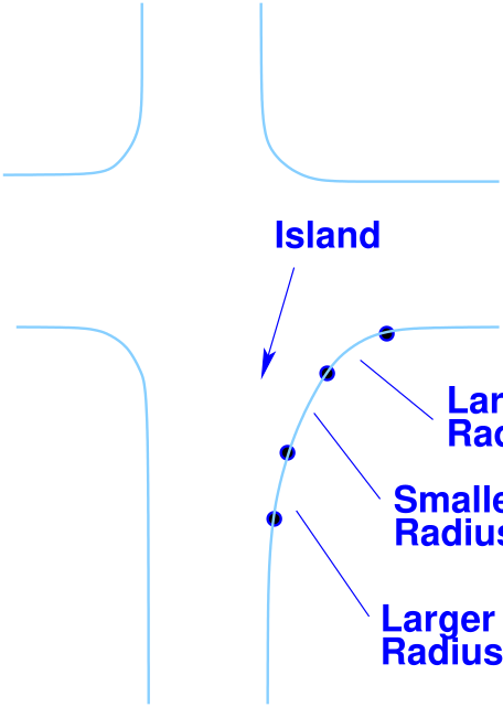
The combination of a simple radius flanked by tapers can often fit the pavement edge more closely to the
design motor vehicle than a simple radius (with no tapers). Figs. 22, 23 and 24 shows the various types
of curves that can be used for a roadway. The closer fit can be important for large design motor
vehicles where effective pavement width is small (due either to narrow pavement or need to
avoid any encroachment), or where turning speeds greater than the design speed are desired.
Figure 22: Various types of curves used for a turning roadway , (a)Simple Radius
Figure 23: Various types of curves used for a turning roadway, (b)Radius and Taper
Figure 24: Various types of curves used for a turning roadway, (c)Turning Roadway
Table. 3 and Table. 4 summarizes design elements for curve/taper combinations that permit various
design motor vehicles to turn, without any encroachment, from a single approach lane into a
single departure lane (Note: W should be determined using the turning path of the design
vehicle)
Table 3: Curve and Taper Corner Design Elements
Angle of Turn
Design Vehicle
Radius
Offset
Taper Length
(Degrees)
(meters)
(OS meters)
(T1 meters)
Passenger Car
7.5
0.6
6
75
Single Unit Truck
13.5
0.6
6
Single Trailer Unit
19.5
0.9
13.5
Passenger Car
6
0.75
7.5
90
Single Unit Truck
12
0.6
6
Single Trailer Unit
18
1.2
18
Passenger Car
6
0.6
-
120
Single Unit Truck
9
0.9
-
Single Trailer Unit
13.5
1.2
18
Table 4: Design elements for Turning Roadways
Angle of Turn
Design Vehicle
Radius(meter)
Offset
(Degrees)
R1-R2-R1
(OS meter)
Passenger Car (P)
30-22.5-30
0.6
75
Single Unit Truck (SU)
36-13.5-36
0.6
Semi-Trailer Unit (WB-50)
45-15-45
2
Passenger Car (P)
30-6-30
0.8
90
Single Unit Truck (SU)
36-12-36
0.6
Semi-Trailer Unit (WB-50)
54-18-54
2
Passenger Car (P)
30-6-30
0.6
120
Single Unit Truck (SU)
30-9-30
0.9
Semi-Trailer Unit (WB-50)
54-12-54
2.6
The width of the roadway can be found out from Table. 5 given below.
Table 5: Width of roadway required for negotiating the turn for different classes of vehicles (W)
Radius on
One-Lane One Way
One-Lane One Way
Two way operation
inner edge
Operation (No
Operation (Having
Either One way or Two
of
provision of passing a
provision of passing a
way (Same Type of vehicle
pavement
stalled vehicle) in meter
stalled vehicle) in meter
in both lanes) in meter
in meter
P
SU
WB-50
P
SU
WB-50
P
SU
WB-50
15
3.9
5.4
7.8
6
8.7
13.2
7.8
10.5
15
22.5
3.9
5.1
6.6
5.7
8.1
10.8
7.5
9.9
12.6
30
3.9
4.8
6.3
5.7
7.5
10.2
7.5
9.3
12
45
3.6
4.8
5.7
5.4
7.2
8.7
7.2
9
10.5
60
3.6
4.8
5.1
5.4
6.9
8.1
7.2
8.7
9.9
90
3.6
4.5
5.1
5.4
6.6
7.5
7.2
8.4
9.3
7 Guidelines for design of Median islands
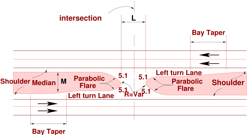
The general guidelines to be followed in the design of median islands (separators of opposing traffic flows)
are:
The approach noses should be offset 0.6 to 1.8 m from through lanes to minimize accidental
impacts.
Shape should be based on design turning paths and island function. (Generally parabolic or
circular arcs are used)
The length of median before the intersection is related to approach speed (normally 3 sec
driving time to intersection). It is also affected by available widths, taper designs and local
constraints.
The width of the medians should serve its primary intended function.
The median should always be provided well past crest vertical curves.
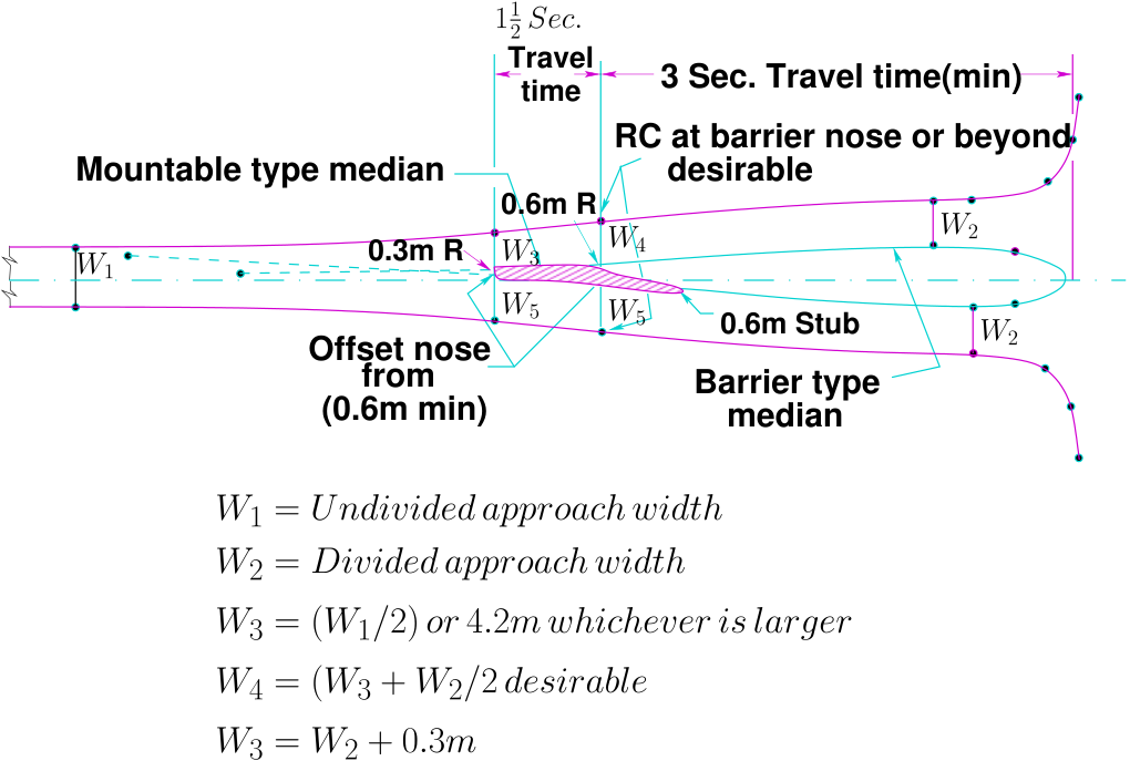
Fig. 25 shows the general design elements of medians provided just at the approach to a intersection.
Figure 25: Design Criteria for raised median approaches to intersections
The required median widths for performing their intended functions are provided by AASHTO and are
shown in Table. 6 below. These widths are empirical and can be applied at an intersection with reasonable
efficiency.
Table 6: Basic median functions and their required width
Function
Width in meter
Minimum
Desirable
Separation of opposing traffic
1.2
3
Provision of pedestrian refuse
1.8
4.2
Provision of storage for left-turn vehicles
4.8
6
Provision for protection of vehicles crossing
7.5
9
through lanes
Provision for U turns, inside to outside lanes
4.8
6
Provision for U-turns, inside to inside lanes
7.8
9
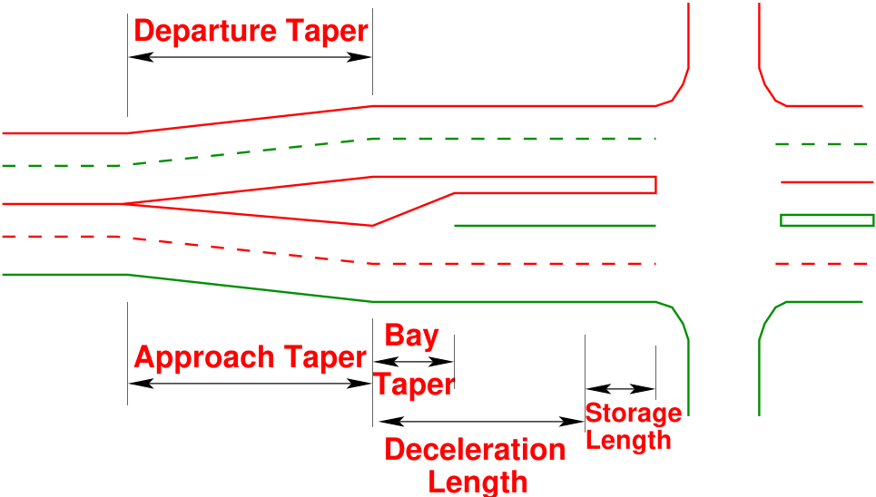
7.1 Auxiliary Lanes
Auxiliary lanes are used under conditions of relatively high traffic volumes in the intersections. In these
cases, traffic congestion problems can be significantly alleviated with auxiliary lanes to handle turning
movements. The median lane should be 12 feet (3.6m), but not less than 10 feet (3.0m) wide and should
be clearly marked for this purpose. Auxiliary lanes can also be introduced to provide for both left turns and right turns at intersections. The
need for such lanes is determined by capacity analysis and the acceptable level of service designated for
the facility. The lanes should be at least 2.7m wide for reconstruction and resurfacing projects and at least
3.0m, preferably 3.6m for new construction projects. Auxiliary lane shoulders can be reduced to 0.6 m
wide on rural sections and 0 m wide on sections with curb and gutter. The length of auxiliary lanes
consists of five components:
Approach Taper
Deceleration Length
Bay Taper
Storage Length, and
Departure Taper.
A typical auxiliary lane with the components are shown in Fig. 26 below.
Figure 26: Components of Auxiliary Lane
These are discussed in detail in the following section.
Approach Taper- The length of the approach taper varies with operating speeds. Guidelines
for determining lengths are: (i) For speeds 70 kmph and over: \(L = 0.6 WS\), and (ii) For speeds under 70
kmph: \(L= WS^2/100\) where, \(L\) is the length of entering taper in m, \(W\) is the width to be tapered in m, and \(S\) is
the operating Speed in kmph.
Deceleration Length- The deceleration length is that required for a comfortable stop of a vehicle
from a speed that is typical of the average running speed on the facility. The Bay Taper
can be considered part of the deceleration length. AASHTO has again given a table
for calculating the decelerating length value from the design speed value (Table. 7).
Table 7: Deceleration length vs Design Speed
Design Speed
Deceleration Length
(kmph)
(m)
40
35
55
45
65
55
70
65
80
95
Bay Taper - This is a straight line taper with ratios varying from 5:1 to 10:1. Higher speed facilities
should generally have longer tapers. Empirically, the minimum and maximum values of bay taper are
taken as 18m and 36m respectively.
Storage Length - The storage length should be sufficiently long to store the number of vehicles
likely to accumulate during the average daily peak period.
At unsignalized intersections, length to be based on the number of vehicles likely to
arrive in an average 2-minute period within the peak hour.
At signalized intersections, the required length depends on the signal cycle length, the
signal phasing arrangement and the rate of arrivals and departures of left turning vehicles.
Departure Taper - The departure taper is normally taken equal in length to that of the approach
taper and should begin opposite the beginning of the Bay Taper.
7.2 Shape of Median Ends
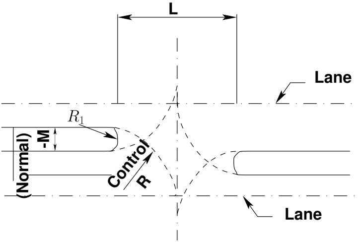
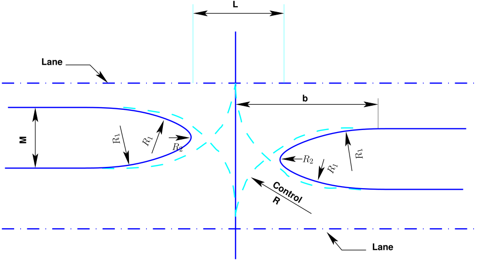
Generally, two types of end shapes are used in practice:-semicircular shapes and bullet nose. The shape
adopted normally depends on the effective median width at the end of the median. The dimensions of the
various parameters for semi-circular and bullet nose ends area as: Semi-circular- \(L = 2 \times Control R\), \(R1 = M/2\). Bullet-nose- \(L = Control R\), \(R1 = M/2\), \( R2 = M/5\) The
criteria for the selection of median end is as given below in Table. 8.
Table 8: Criteria for selection of median end shape
Effective Median Width
Median End Shape
Less than 3m
Semi-circular
3m - 20m
Bullet Nose
Over 20m
Treated as a separate intersection
Figure 27: Shapes of Median ends, (a)Semi-circular
Figure 28: Shapes of Median ends, (b)Bullet-nose
The two shapes are illustrated in Figs. 27 and 28. The designer should evaluate each
intersection to determine the best median opening shape that will accommodate the design
vehicle.
7.3 Design of Median Openings
Median openings, sometimes called crossovers, provide for vehicular crossings of the median at designated
locations. The design of a median opening should be based on traffic volumes and types of turning
vehicles. Cross and turning traffic must operate in conjunction with the through traffic on the divided
highway. This requirement makes it necessary to know the volume and composition of all movements
occurring simultaneously during the design hours. The design of a median opening becomes a matter of
considering what traffic is to be accommodated, choosing the design vehicle to use for layout controls for
each cross and turning movement, investigating whether larger vehicles can turn without undue
encroachment on adjacent lanes and, finally, checking the intersection for capacity. If the capacity is
exceeded by the traffic load, the design must be expanded, possibly by widening or otherwise adjusting
widths for certain movements. Traffic control devices such as yield signs, stop signs or traffic
signals may be required to regulate the various movements effectively and to improve the
efficiency of operations. Median openings at close intervals on other types of highways create
interference with fast through traffic. Median openings should be spaced at intervals no closer than
500 m. However, if a median opening falls within 100 m of an access opening, it should be
placed opposite the access opening. Also, the length of median opening varies with width
of median and angle of intersecting roads. Fig. 29 shows the intersection median opening.
Figure 29: Intersection Median Opening
The median openings for the different classes of design vehicle are as given in the Table. 9.
Table 9: Median Openings
Width of
Passenger Car
Single Unit Truck
Single Trailer Unit
Median(m)
Semi - circular
Bullet nose
Semi - circular
Bullet nose
Semi - circular
Bullet nose
1.2
22.8
22.8
28.8
28.8
43.8
36.6
1.8
22.2
18
28.2
22.8
43.2
34.5
2.4
21.6
15.9
27.6
20.4
42.6
33
3
21
14.1
27
18.6
42
31.5
3.6
20.4
12.9
26.4
17.4
41.4
30
4.2
19.2
12
25.8
15.9
40.8
28.8
4.8
18
12
25.2
15
40.2
27.6
6
16.8
12
24
13.2
39
25.5
8 Developing a Channelization Plan
Channelization is more of an art rather than science. Every intersection requires a special
study because of variations in physical dimensions, turning movements, traffic and pedestrian
volumes, type of traffic control etc.
In the next step several island configurations are considered and compared. Then a choice is
made between curbed, raised islands and flush Channelization or pavement markings.
Next it must be checked that the design is compatible to handle turning movements of large
vehicles. Also, it should be such that the vehicles are guided in normal wheel paths, so that
the island does not create an obstruction in the roadway.
Signing and marking are redesigned to guide drivers and avoid confusion.
The final plan includes details of civil and electrical engineering features (like drainage
facilities, curbs, lighting, signals etc.) required for the project completion.
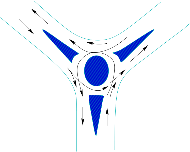
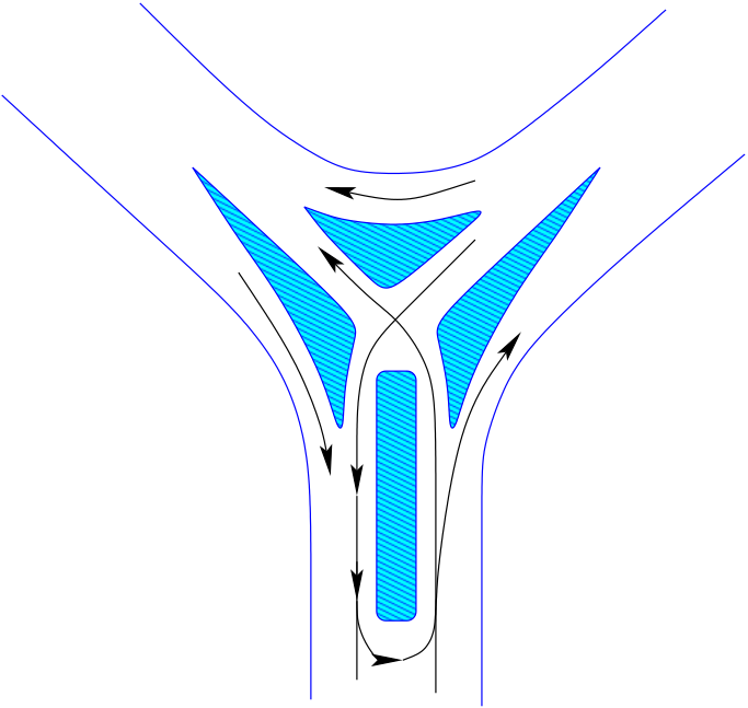
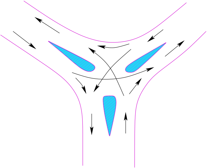
9 Typical Channelization Examples
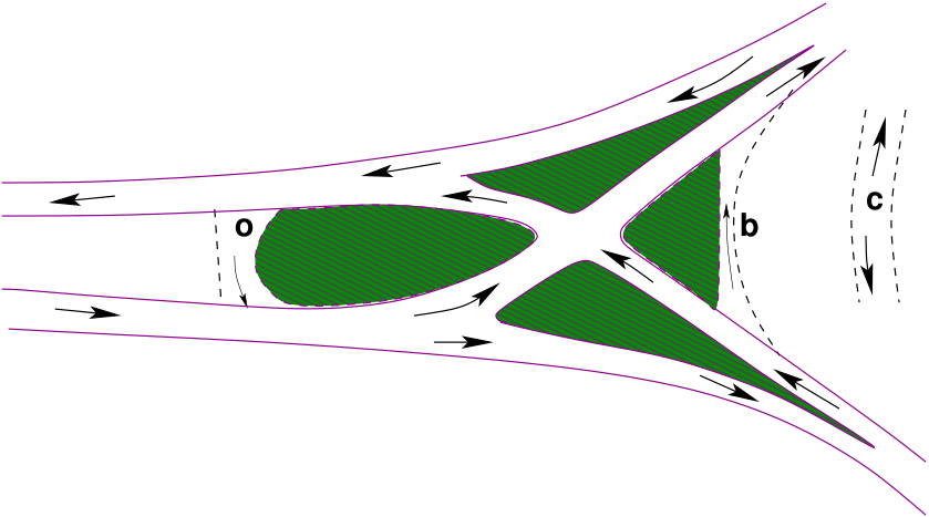
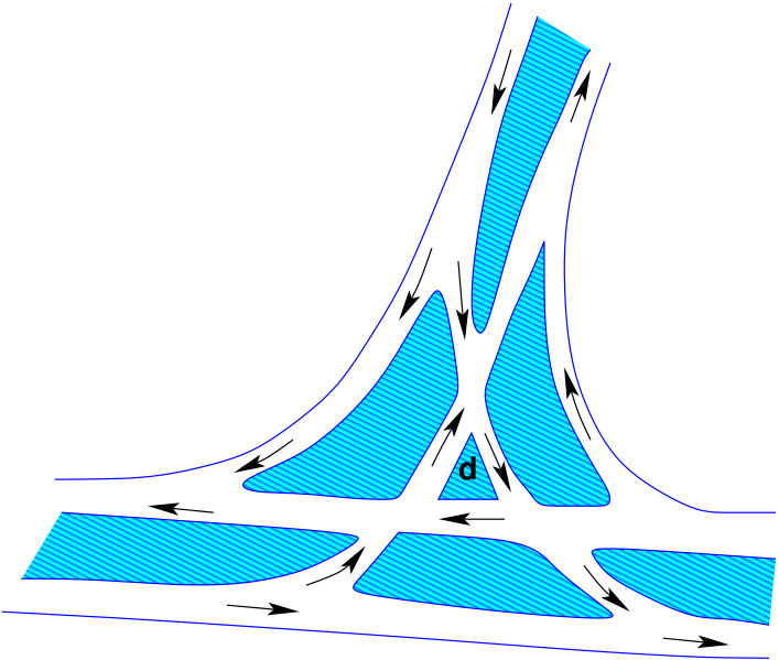
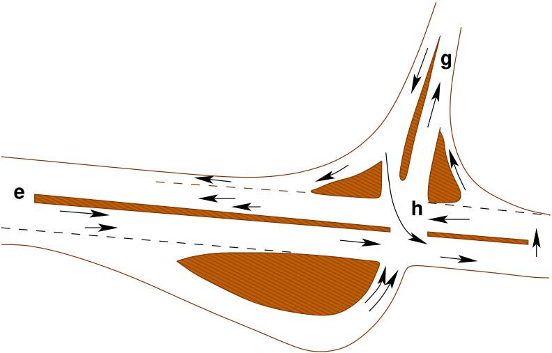
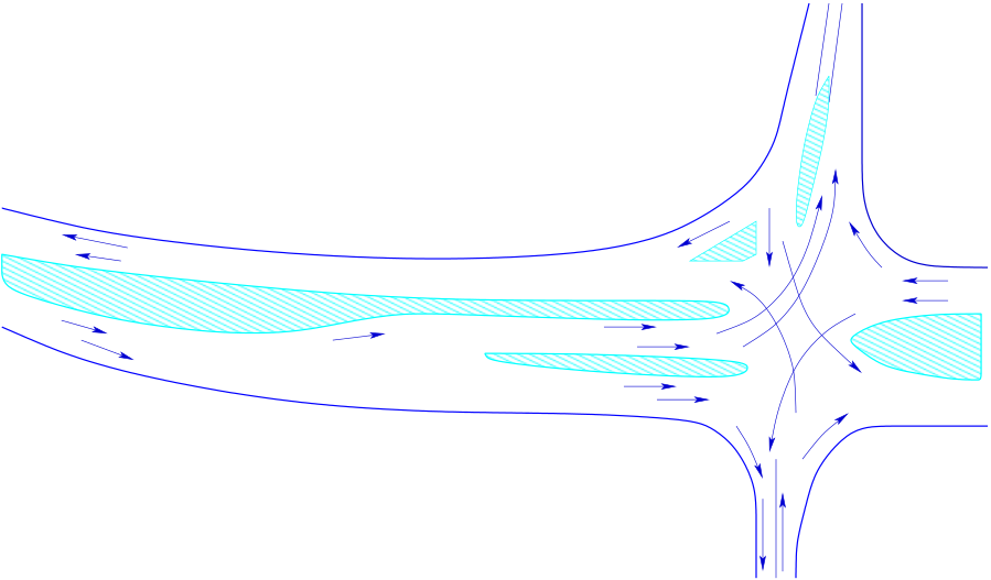
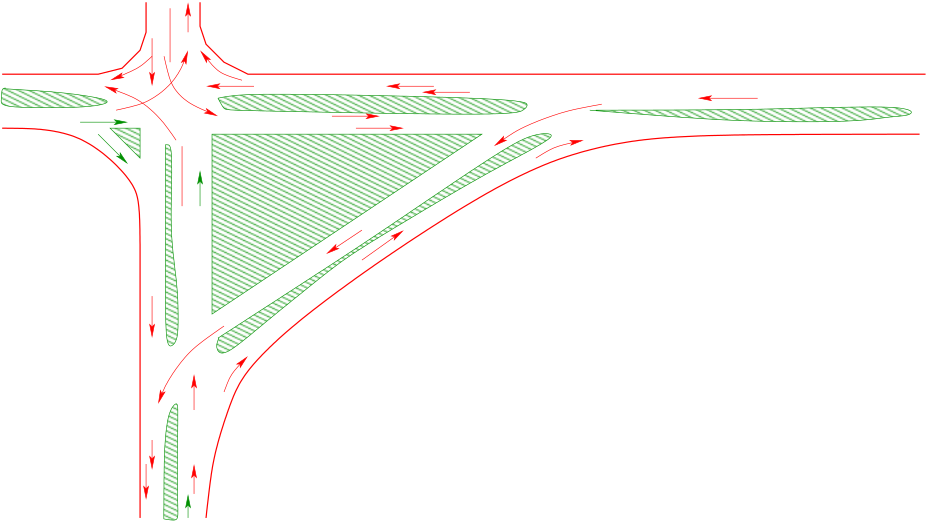
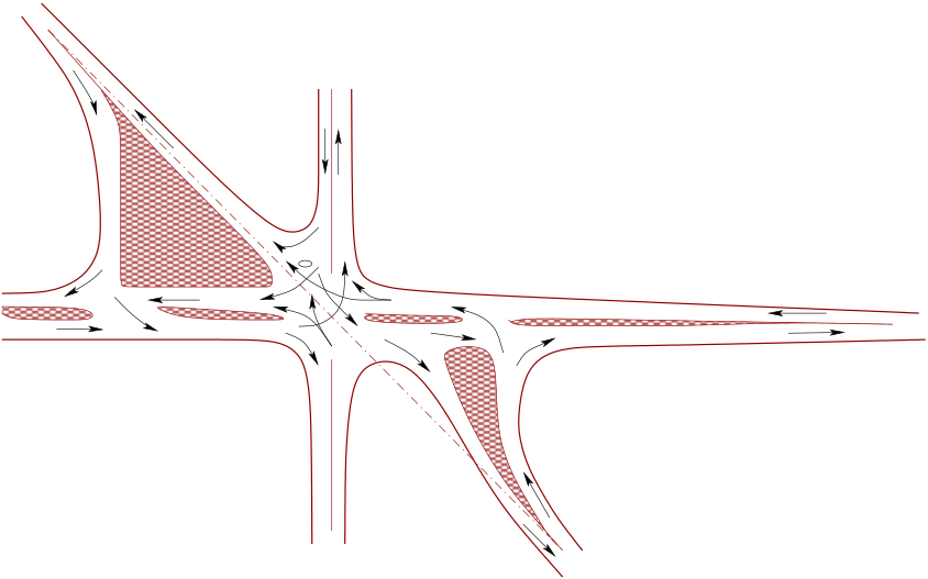
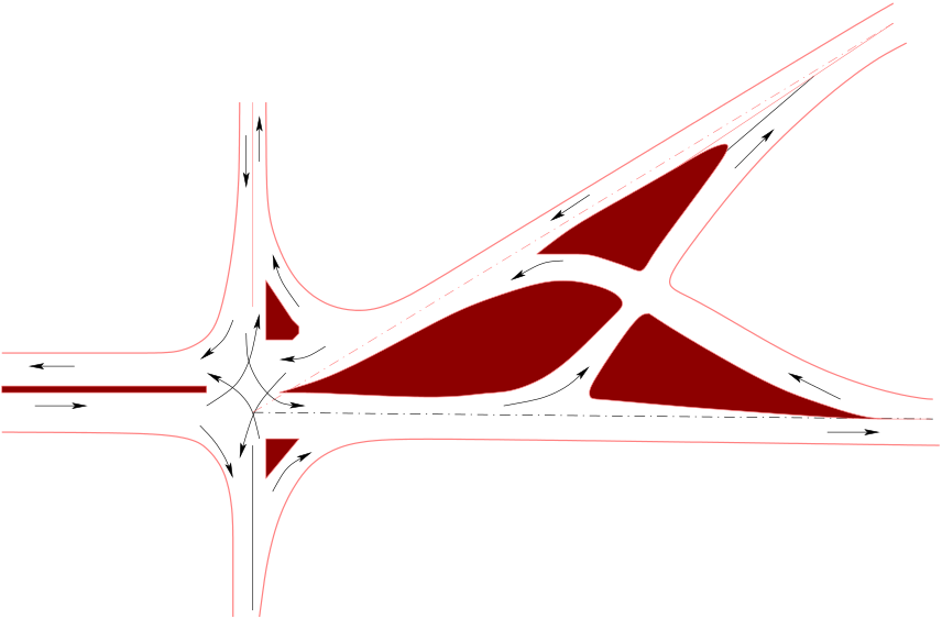
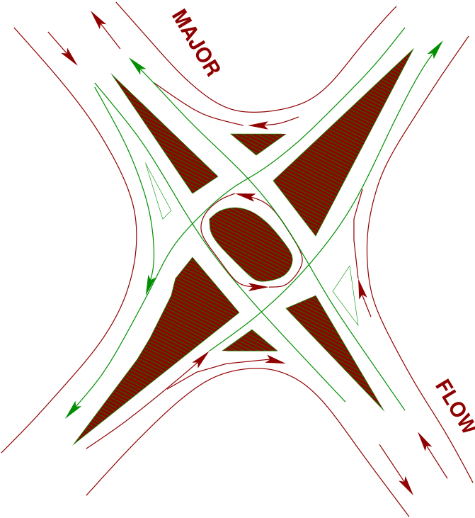
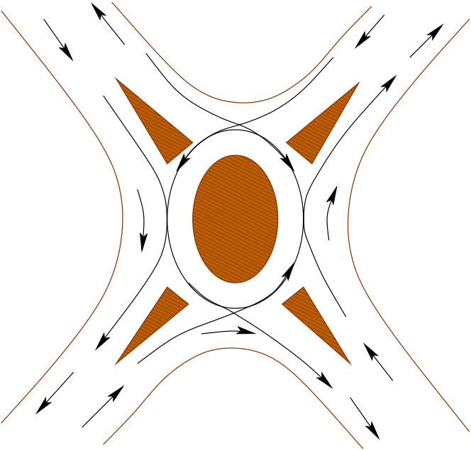
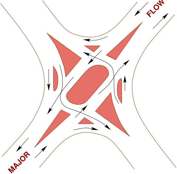
Some typical Channelization ways used in practice are as given below. Figs. 30 to 41 indicate both
normal Channelization and high type Channelization techniques for various intersections and situations.
Figure 30: Channelization for Y Intersections, (a)For low Flows
Figure 31: Channelization for Y Intersections, (b)For High Flows
Figure 32: Channelization for T Intersections, (a)For low Flows
Figure 33: Channelization for T Intersections, (b)For High Flows
Figure 34: Channelization for T or Y Intersections (Channelized-High Type)
Figure 35: Channelization for T or Y Intersections (Channelized-High Type)
Figure 36: Channelization for T or Y Intersections (Channelized-High Type)
Figure 37: Channelization for T or Y Intersections (Channelized-High Type)
Figure 38: Channelization for 4-Leg Intersections (Channelized-High Type)
Figure 39: Channelization for 4-Leg Intersections (Channelized-High Type)
Figure 40: Channelization for Multi - leg Intersections
Figure 41: Channelization for Multi - leg Intersections
10 Turning Vehicle Templates
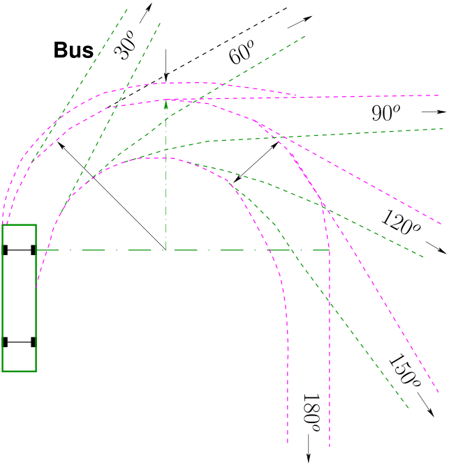
In the design of intersections the turning paths of vehicles assumes utmost importance. The turning paths
of design vehicles are given in transparent templates such as the one shown in Fig. 17 and
Fig. 18. These templates are placed over the intersection plan to trace the path of the turning
vehicle. Once this is done, proper islands and other traffic control devices can be designed.
As per AASHTO, the turning templates are drawn at an approximate scale of 1”=50’. The
radius of the template is measured to the outside front wheel path at the beginning of the
curve. The design vehicle for the purpose can be taken out of a list of 16 different types of
vehicles suggested by AASHTO. The dimensions of some of the design vehicles are given in
Table. 10 below. The templates are applied to the layout of intersections and other facilities in
accommodating vehicle maneuvers, including driveways, car parking, truck loading and bus
terminals.
Table 10: Dimensions of some common Design vehicles
Design Vehicle Type
Symbol
Overall Dimension
Height (m)
Width (m)
Length (m)
Passenger Car
P
1.3
2.1
5.8
Single Unit Truck
SU
4.1
2.6
9.1
Single Unit Bus
BUS
4.1
2.6
12.1
Intermediate Semi-Trailer
WB-15
4.1
2.6
16.7
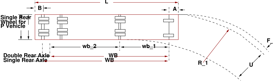
Here we shall take the cases of a passenger car (P) and a single unit truck (BUS) as the design vehicles.
The various design elements and their dimensions are shown in Fig. 42 and Table. 11 respectively.
Figure 42: Design vehicle Dimensions and Turning Properties
Table 11: Design vehicle Dimensions and Turning Properties for \(90^o\) turns
Vehicle
WB
Minimum Turn
Designation
L(m)
(m)
A(m)
B(m)
W(m)
U(m)
U** (m)
FA
RT
(m)
(m)
(m)
BUS
12.1
7.5
2
2.5
2.6
2.6
4.98
1.25
13
Passenger Car (P)
5.8
3.4
0.9
15
2.1
1.8
2.61
0.6
7.5
The templates were developed to include a variety of angles, with specific configurations for every 30
degrees of turn (30, 60, 90, 120, 150 and 180). By special manipulation of the template, any degree of
turning can be produced within an overall range of 20 to 200 degrees. The four variables-vehicle type,
turning radius, angle of turn and scale-provide full flexibility in the use of turning vehicle templates for
layout and design. To permit greater latitude in maneuvering of buses, single unit trucks and
passenger cars, special bar tenders are included, consisting of turning radii in the range of 13 to 50
meters for the first two and 5.5 to 30 meters for the last type of vehicles which are outside
the scope of this discussion. The list of templates for bus and passenger cars is shown in the
Table. 12.
Table 12: List of Templates
Vehicle Type
Scales
Turning Radius-m
Average Size-cm
1:250
R= 13 & 18
\(20 \times 25\)
BUS
1:500
R= 13 & 18
\(18 \times 18\)
1:250
R=13 to 50
\(20 \times 25\)
Bar Template
1:250
R=7.5
1\(8 \times 18\)
Passenger car
1:250
R=7.5 to 30
\(18 \times 18\)
Bar template
The templates for the Passenger Car (P) and Bus are as shown in Fig. 43, 44 below.
Figure 43: Design Template for Passenger Car (P)
Figure 44: Design Template for Bus
10.0.1 Numerical example 1
Provide Channelization for an intersection having EW as the major road. The major and minor roads
intersect at right angles. The design vehicle is WB-50 (R=25m) and design speed is 45 kmph. The
intersection is unsignalized. EW road has 2 lanes in each direction and NS has 1 lane for each direction.
Take lane width =3.6 m. Provide bullet nose median ends. Also provide channelizing island for free right
for WS bound traffic.
Solution
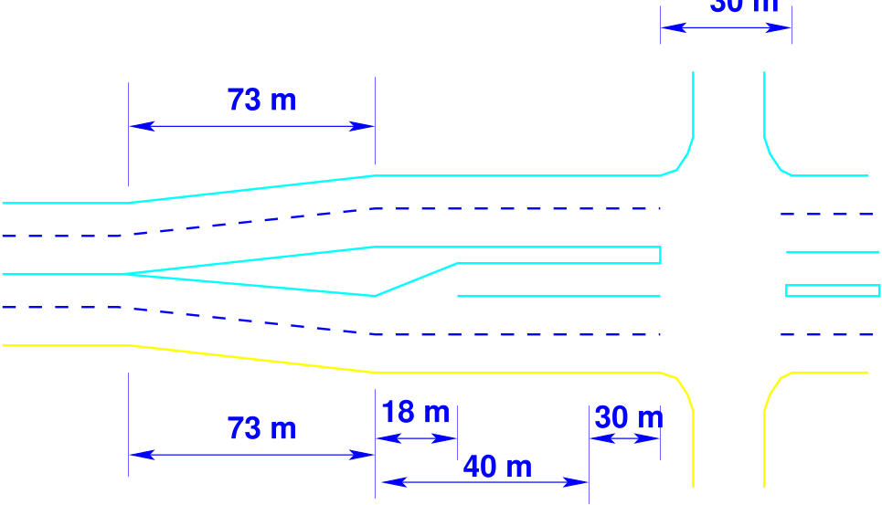
: The approach taper for auxiliary lane is equal to \(3.6 \times 45 \times 45/100 = 73~m\). The deceleration Taper is taken as 40 m.
Considering a 1:10 taper, the Bay Taper is found out to be 18 m. Let the storage length = 30
m (say). Now from Table. 9, it is found that for bullet nose median end, Median Opening
= 30 m. The dimensions of all the components of the auxiliary lane are shown in Fig. 45.
Figure 45: Dimensions of components of the auxiliary lane for the intersection
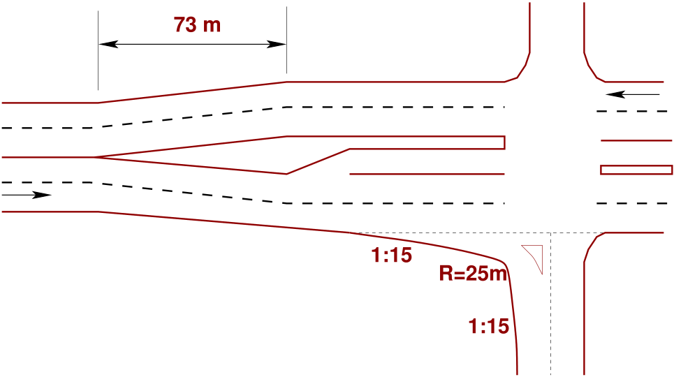
The width required for the WB- 50 semi-trailer unit is found to be about 6.5 m. Additional 0.5 m is
provided on the outer side and 0.3 m is provided on the inner side away from the edge of the island. For
the turning roadway for the W-S direction, the single offset method is used. At 0.3 + 0.5 + 6.5 = 7.3 m
from the island edge, a circle of radius 25 m is laid out. Then two tapers of slope 1:15 is laid out on either
side of the arc to join with the straight edge on either side. Thus the Channelization is provided for
the W-S approach. Similar method can be used for designing the Channelization schemes of
the other directions as well. The Channelization for the W-S approach is shown in Fig. 46.
Figure 46: Channelization for the W-S direction with traffic island
10.0.2 Numerical example 2
Following the principles of Channelization suggest suitable island schemes for the following intersections
(considering both high relative speed and low relative speed) (Figs. 47, 48)
This chapter presents one of the simple and cost effective way of intersection control, namely the
Channelization. This is normally adopted for low and medium volume roads. The chapter contains the
design principles, traffic islands, and median.
Exercises
Channelize the intersection given in the Figure 55 with the help of a neat sketch. Show the
paths of movements by short arrows. All the roads are bi-directional. Assume the flows are
very high.
FIGURE MISSING
Figure 55: Intersection layout
References
Wolfgang S Homburger and James H Kell. Fundamentals of Traffic Engineering. Institute
of Transportation Studies, University of California, Berkeley, 1997.
S K Khanna and C E G Justo. Highway Engineering. Nem Chand and Bros, Roorkee, 2001.
Theodore M Matson, Wilbur S Smith, and Frederick W Hurd. Traffic Engineering. McGraw
Hill Book Company, New York, 1955.
William R McShane, Roger P Roess, and Elena S Prassas. Traffic Engineering.
Prentice-Hall, Inc, Upper Saddle River, New Jesery, 1998.
T R Neuman. Intersection channelization design guide. Transportation Research Board.
TRB NCHRP R 279, Washington, D.C., 1985.
R J Paquette, N Ashford, and P H Wright. Transportation Engineering : Planning and
Design. John Wiley, New York, 1972.
Acknowledgments
I wish to thank several of my students and staff of NPTEL for their contribution in this lecture. I wish to
thank specially my student Mr. Pratik Patra for his assistance in developing the lecture note, and my staff
Ms. Reeba in typesetting the materials. I also appreciate your constructive feedback which may be sent to
tvm@civil.iitb.ac.in. Prof. Tom V. Mathew, Department of Civil engineering, Indian Instiute of
Technology Bombay, India.