Figure 1: Traffic operations in a rotary *
Rotary intersections or round abouts are special form of at-grade intersections laid out for the movement of traffic in one direction around a central traffic island. Essentially all the major conflicts at an intersection namely the collision between through and right-turn movements are converted into milder conflicts namely merging and diverging. The vehicles entering the rotary are gently forced to move in a clockwise direction in orderly fashion. They then weave out of the rotary to the desired direction. The benefits, design principles, capacity of rotary etc. will be discussed in this chapter.
The key advantages of a rotary intersection are listed below:
Although rotaries offer some distinct advantages, there are few specific limitations for rotaries which are listed below.
Because of the above limitation, rotaries are not suitable for every location. There are few guidelines that help in deciding the suitability of a rotary. They are listed below.
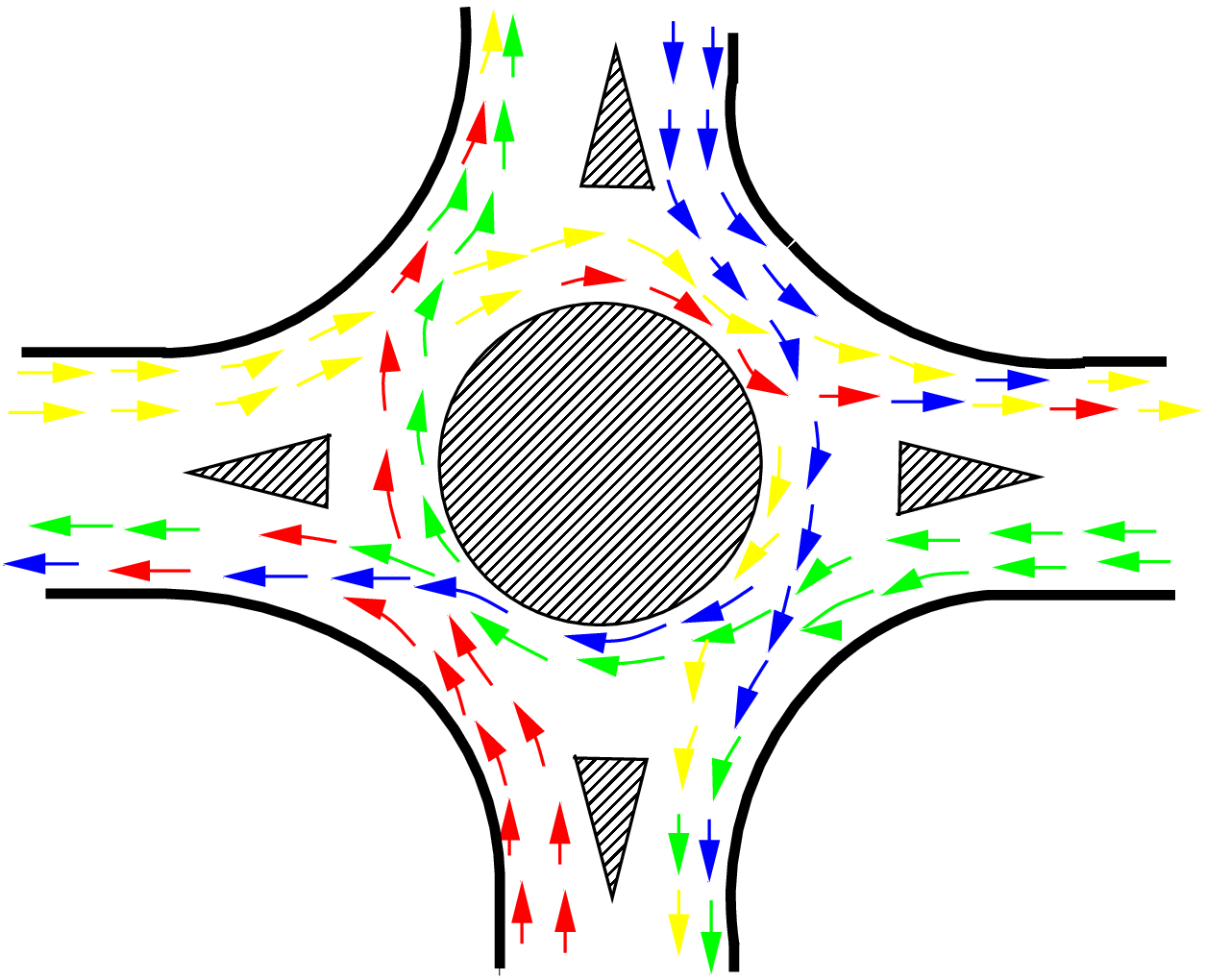
As noted earlier, the traffic operations at a rotary are three; diverging, merging and weaving. All the other conflicts are converted into these three less severe conflicts.
These movements are shown in figure 1. It can be observed that movements from each direction split into three; left, straight, and right turn.
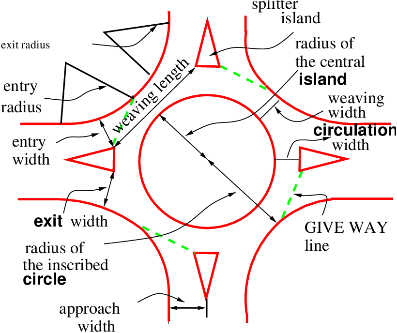
The design elements include design speed, radius at entry, exit and the central island, weaving length and width, entry and exit widths. In addition the capacity of the rotary can also be determined by using some empirical formula. A typical rotary and the important design elements are shown in figure 2
All the vehicles are required to reduce their speed at a rotary. Therefore, the design speed of a rotary will be much lower than the roads leading to it. Although it is possible to design roundabout without much speed reduction, the geometry may lead to very large size incurring huge cost of construction. The normal practice is to keep the design speed as 30 and 40 kmph for urban and rural areas respectively.
The radius at the entry depends on various factors like design speed, super-elevation, and coefficient of friction. The entry to the rotary is not straight, but a small curvature is introduced. This will force the driver to reduce the speed. The entry radius of about 20 and 25 meters is ideal for an urban and rural design respectively.
The exit radius should be higher than the entry radius and the radius of the rotary island so that the vehicles will discharge from the rotary at a higher rate. A general practice is to keep the exit radius as 1.5 to 2 times the entry radius. However, if pedestrian movement is higher at the exit approach, then the exit radius could be set as same as that of the entry radius.
The radius of the central island is governed by the design speed, and the radius of the entry curve. The radius of the central island, in practice, is given a slightly higher radius so that the movement of the traffic already in the rotary will have priority. The radius of the central island which is about 1.3 times that of the entry curve is adequate for all practical purposes.
The entry width and exit width of the rotary is governed by the traffic entering and leaving the intersection and the width of the approaching road. The width of the carriageway at entry and exit will be lower than the width of the carriageway at the approaches to enable reduction of speed. IRC suggests that a two lane road of 7 m width should be kept as 7 m for urban roads and 6.5 m for rural roads. Further, a three lane road of 10.5 m is to be reduced to 7 m and 7.5 m respectively for urban and rural roads.
The width of the weaving section should be higher than the width at entry and exit. Normally this will be one lane more than the average entry and exit width. Thus weaving width is given as,
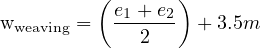 | (1) |
where e1 is the width of the carriageway at the entry and e2 is the carriageway width at exit.
Weaving length determines how smoothly the traffic can merge and diverge. It is decided based on many factors such as weaving width, proportion of weaving traffic to the non-weaving traffic etc. This can be best achieved by making the ratio of weaving length to the weaving width very high. A ratio of 4 is the minimum value suggested by IRC. Very large weaving length is also dangerous, as it may encourage over-speeding.
The capacity of rotary is determined by the capacity of each weaving section. Transportation road research lab (TRL) proposed the following empirical formula to find the capacity of the weaving section.
![280w[1+ e-][1- p]
Qw = --------ww----3-
1 + l](web1x.png) | (2) |
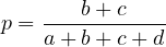
where e is the average entry and exit width, i.e,  , w is the weaving width, l is the length
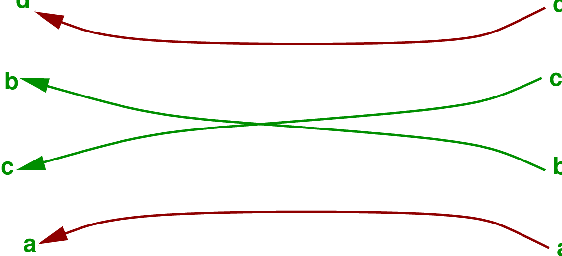
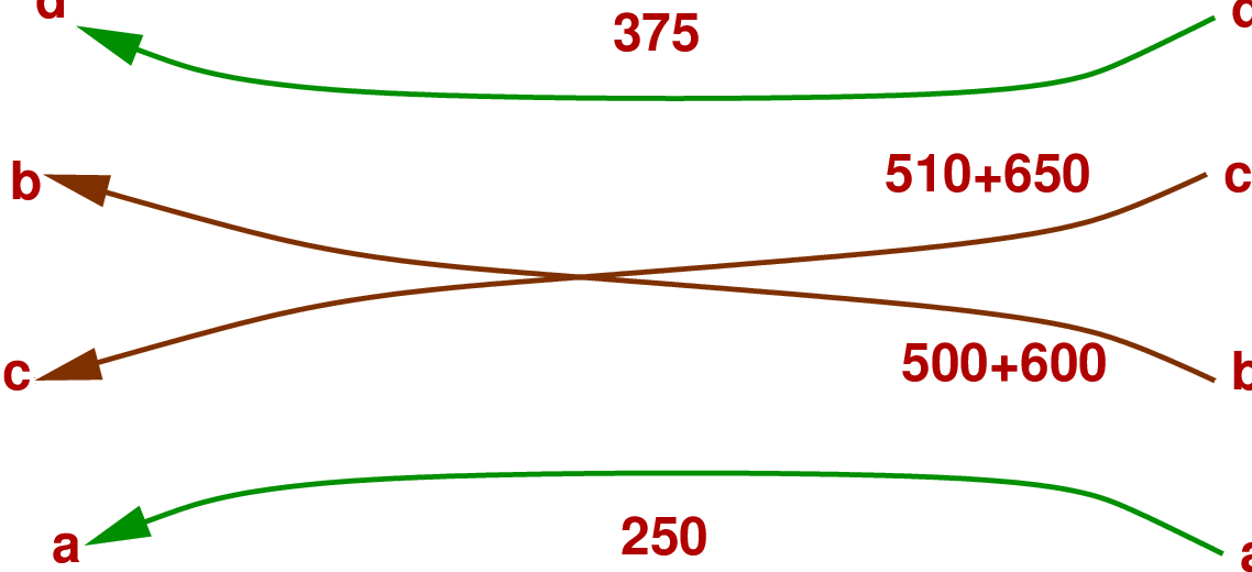
of weaving, and p is the proportion of weaving traffic to the non-weaving traffic. Figure 3
shows four types of movements at a weaving section, a and d are the non-weaving traffic and
b and c are the weaving traffic.
, w is the weaving width, l is the length
of weaving, and p is the proportion of weaving traffic to the non-weaving traffic. Figure 3
shows four types of movements at a weaving section, a and d are the non-weaving traffic and
b and c are the weaving traffic.
Therefore,
 | (3) |
This capacity formula is valid only if the following conditions are satisfied.
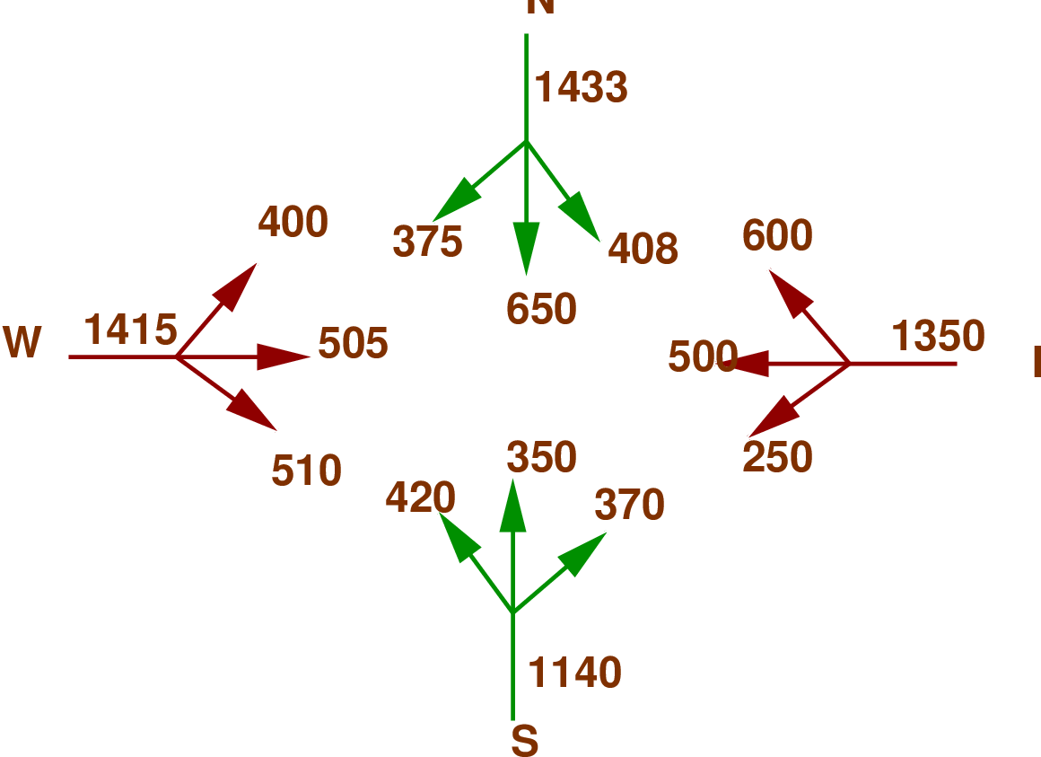
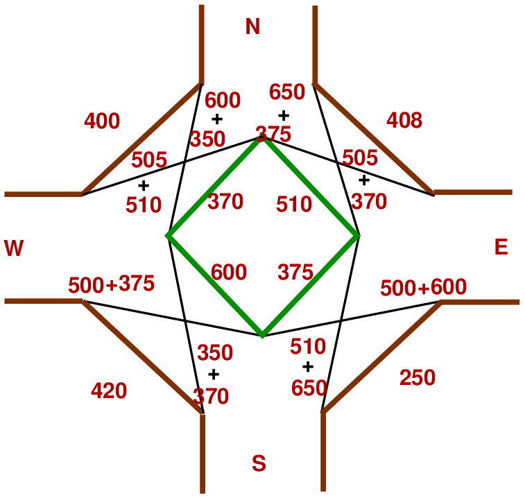
The width of a carriage way approaching an intersection is given as 15 m. The entry and exit width at the rotary is 10 m. The traffic approaching the intersection from the four sides is shown in the figure 4 below. Find the capacity of the rotary using the given data.
 ] + 3.5 = 13.5 m
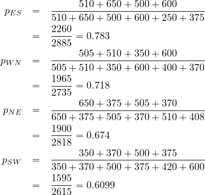
![QES = 280×-13.5[11-++-1113503..455][1--0.7833]
= 2161.2 veh∕hr.](web6x.png)
Traffic rotaries reduce the complexity of crossing traffic by forcing them into weaving operations. The shape and size of the rotary are determined by the traffic volume and share of turning movements. Capacity assessment of a rotary is done by analyzing the section having the greatest proportion of weaving traffic. The analysis is done by using the formula given by TRL.
| Approach | Left turn | Straight | Right turn |
| North | 500 | 800 | 300 |
| South | 400 | 350 | 450 |
| East | 250 | 400 | 500 |
| West | 300 | 450 | 500 |
| Approach | Left turn | Straight | Right turn |
| North | 500 | 800 | 300 |
| South | 400 | 350 | 450 |
| East | 250 | 400 | 500 |
| West | 300 | 450 | 500 |
I wish to thank several of my students and staff of NPTEL for their contribution in this lecture. I also appreciate your constructive feedback which may be sent to tvm@civil.iitb.ac.in
Prof. Tom V. Mathew
Department of Civil Engineering
Indian Institute of Technology Bombay, India
_________________________________________________________________________
Wednesday 27 September 2023 11:12:34 PM IST